Relief valve, method of manufacturing relief valve, and fuel cell

a technology of relief valves and valve components, which is applied in the field of relief valves, method of manufacturing relief valves, and fuel cells, can solve the problems of large energy requirements, valve members vibrating, and affecting the operation of the valve, and achieve the effects of suppressing leakage, small size, and simple structur

Inactive Publication Date: 2007-02-01
CANON KK
View PDF9 Cites 52 Cited by
  • Summary
  • Abstract
  • Description
  • Claims
  • Application Information

AI Technical Summary

Benefits of technology

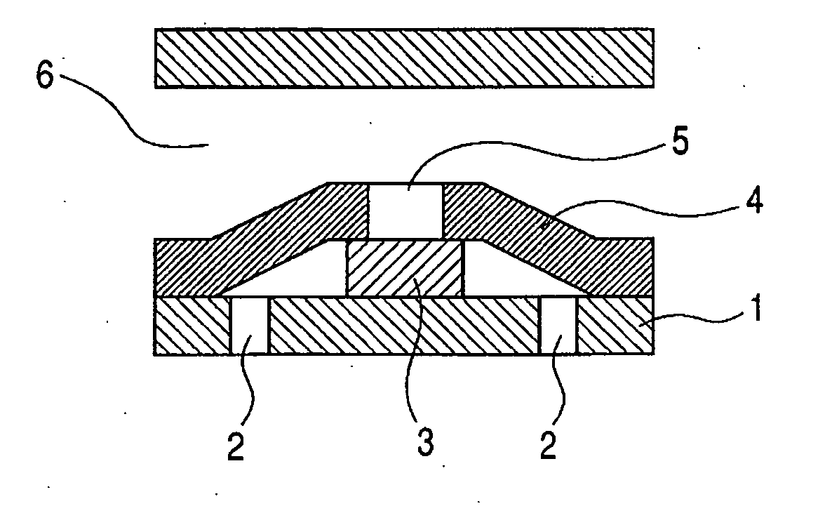
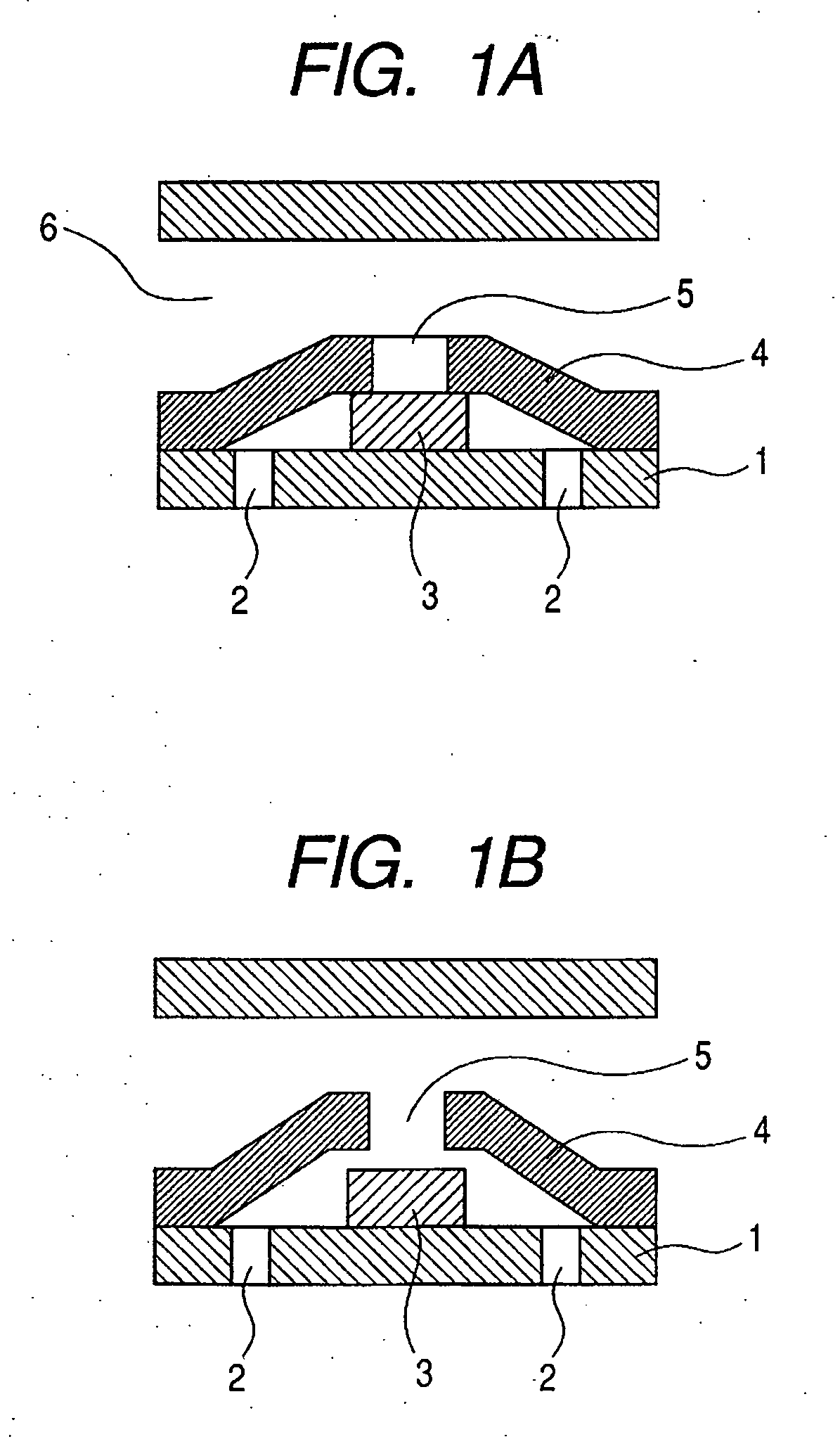
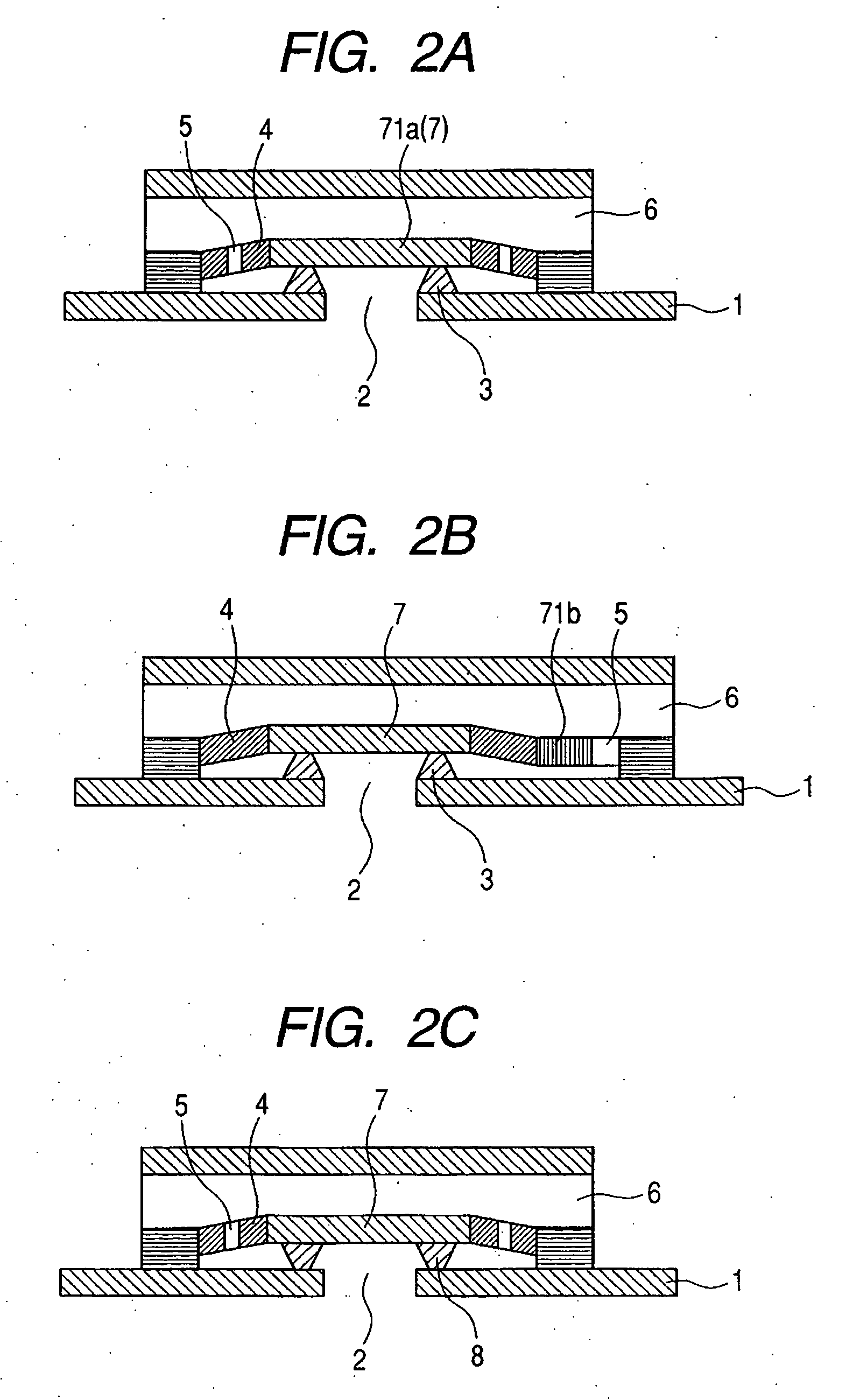
[0015] Another object of the present invention is to provide a relief valve that is small in size and simple in structure and has an outlet disposed at an opposite side of an inlet through a diaphragm by providing a flow path through the diaphragm or a support portion of the diaphragm.
[0016] Another object of the present invention is to provide a method of manufacturing a relief valve for pressure adjustment which significantly suppresses leakage from a gap between semiconductor wafer members by joining the semiconductor wafer members with each other to manufacture the valve.

Problems solved by technology

However, because the direct acting type operates excessively sensitively to the pressure, there may generate a chattering phenomenon that a valve member vibrates depending on a use pressure region.
In a case of liquefying hydrogen, there arise problems in that a large energy is required and liquefied hydrogen is naturally gasified and leaked.
A conventional mechanical processing technique / assembling technique do not have enough precision to fabricate a super-small relief valve, so it is very difficult to manufacture the super-small relief valve.
Also, there arises a problem of high manufacturing costs.
Also, there is no relief valve among the microvalve types that are fabricated by using the conventional semiconductor processing technique.
For this reason, in a case where a direction of the flow path after the outlet is desired to be led to a direction different from the inlet with respect to the diaphragm, there arises a problem in that the structure becomes complicated.
Also, the microvalve formed by using the conventional semiconductor processing technique is manufactured to be the active driving type in many cases, and does not have a structure which can perform an optimum pressure setting as a relief valve.

Method used


Image

  • Relief valve, method of manufacturing relief valve, and fuel cell
  • Relief valve, method of manufacturing relief valve, and fuel cell
  • Relief valve, method of manufacturing relief valve, and fuel cell

Examples


example 1

[0076] A description will be given of the first method of manufacturing the relief valve of the present invention by using the semiconductor processing technique. The relief valve of the present invention is manufactured by finally releasing a valve member after a step of fabricating a fluid inlet and a valve seat in a first silicon wafer, a step of fabricating a diaphragm and a fluid outlet in a second silicon wafer, and a step of joining the first silicon wafer and the second silicon wafer.

[0077]FIGS. 4A to 4Q are process diagrams showing a method of manufacturing a relief valve according to Example 1 of the present invention. The method of manufacturing the relief valve according to the present invention will be described.

[0078] The first step shown in FIG. 4A is a step of forming a mask of the diaphragm and the valve member in the first silicon wafer. A both-side polished silicon wafer 201 having a thickness of 300 μm is used for the wafer. First, two aluminum masks are sequen...

example 2

[0110] A description will be given of the second method of manufacturing the relief valve of the present invention by using a semiconductor processing technique. The flow of the steps is roughly the same as that of Example 1.

[0111]FIGS. 5A to 5Q are step diagrams showing a method of manufacturing a relief valve according to Example 2 of the present invention. In the first step of Example 2, a mask pattern is formed so that a mask 204 is thicker than a mask 203 as shown in FIG. 5A. Subsequently, the second to fifth steps are advanced as shown in FIGS. 5B to SE, the valve member 212 becomes thicker than the surroundings.

[0112] After that, the same steps as the sixth to eighth steps of Example 1 are conducted to form a flow path 213. In this case, a mask pattern in the ninth step according to Example 2 is changed as shown in FIG. 5F. Subsequently, a fluid inlet 215 is formed through the tenth and eleventh steps as shown in FIG. 5G and FIG. 5H. The twelfth to fourteenth steps of Examp...

example 3

[0114] A description will be given of the third method of manufacturing the relief valve of the present invention by using the semiconductor processing technique. The flow of the steps is roughly the same as in Example 1.

[0115]FIGS. 6A to 6H are steps diagrams showing a method of manufacturing a relief valve according to Example 3 of the present invention. In the structure of Example 3, the value seat has a fluid inlet, and the diaphragm has a flow path.

[0116] The first to fifth steps of Example 1 are conducted to form a diaphragm portion. Then, the mask pattern in the sixth step is changed as shown in FIG. 6A, and subsequently the seventh and eighth steps are conducted as shown in FIGS. 6B and 6C, to thereby form a flow path in the diaphragm 211. The ninth to eleventh steps of Example 2 are first conducted on the second silicon wafer, and the mask pattern in the twelfth step is changed as shown in FIG. 6D, to thereby form the fluid inlet 215 in the valve seat 214 in the thirteent...


PUM

PropertyMeasurementUnit
densityaaaaaaaaaa
thicknessaaaaaaaaaa
pressureaaaaaaaaaa

Abstract

Provided is a relief valve that is small in size and has a simple structure in which a flow path is provided so as to penetrate a diaphragm or a support portion of the diaphragm, and an outlet is located at an opposite side of an inlet through the diaphragm. The relief valve for pressure adjustment is made of a semiconductor wafer and operates in a case where a pressure at a fluid inlet is higher than a pressure at a fluid outlet by a pressure higher than a set pressure value, the relief valve including a flow path communicating the fluid inlet with the fluid outlet and a diaphragm for opening and closing the flow path by deformation utilizing a differential pressure between the fluid inlet and the fluid outlet, wherein the flow path penetrates the diaphragm or is disposed at a side surface of the diaphragm, the diaphragm and the valve seat are in contact with each other, and the flow path is opened and closed by deformation of the diaphragm.

Description

BACKGROUND OF THE INVENTION [0001] 1. Field of the Invention [0002] The present invention relates to a relief valve that is manufactured by using a semiconductor processing technology, a method of manufacturing the relief valve, and a fuel cell. Specifically, the present invention relates to a relief value having a direct acting type diaphragm, and a small-sized polymer electrolyte membrane fuel cell having the relief valve mounted thereon and several milliwatts to several hundreds watts in power generation, which can be mounted on a small electric instrument. [0003] 2. Related Background Art [0004] Up to now, various types of relief valves have been manufactured by using a mechanical processing technology. Those relief values are roughly classified into a direct acting type and a pilot type. The direct acting type has an advantage that a structure thereof is simpler than that of the pilot type. Also, the direct acting type is frequently used in a case where an operating fluid is a ...

Claims


Application Information

Patent Timeline
Patent Type & Authority Applications(United States)
IPC IPC(8): H01M8/00
CPCF15B2201/205F15B2201/31F16K99/0001F16K99/0015F16K99/0034F16K99/0057Y02E60/50F16K2099/008F16K2099/0082H01M8/04089H01M8/04432H01M8/04783F16K2099/0074Y02P70/50F16K15/144
Inventor NAKAKUBO, TORU
Owner CANON KK
Why Eureka
Try Eureka