

Burner for premix-type combustion
- Summary
- Abstract
- Description
- Claims
- Application Information
AI Technical Summary
Benefits of technology
Problems solved by technology
Method used
Image

Examples
Embodiment Construction
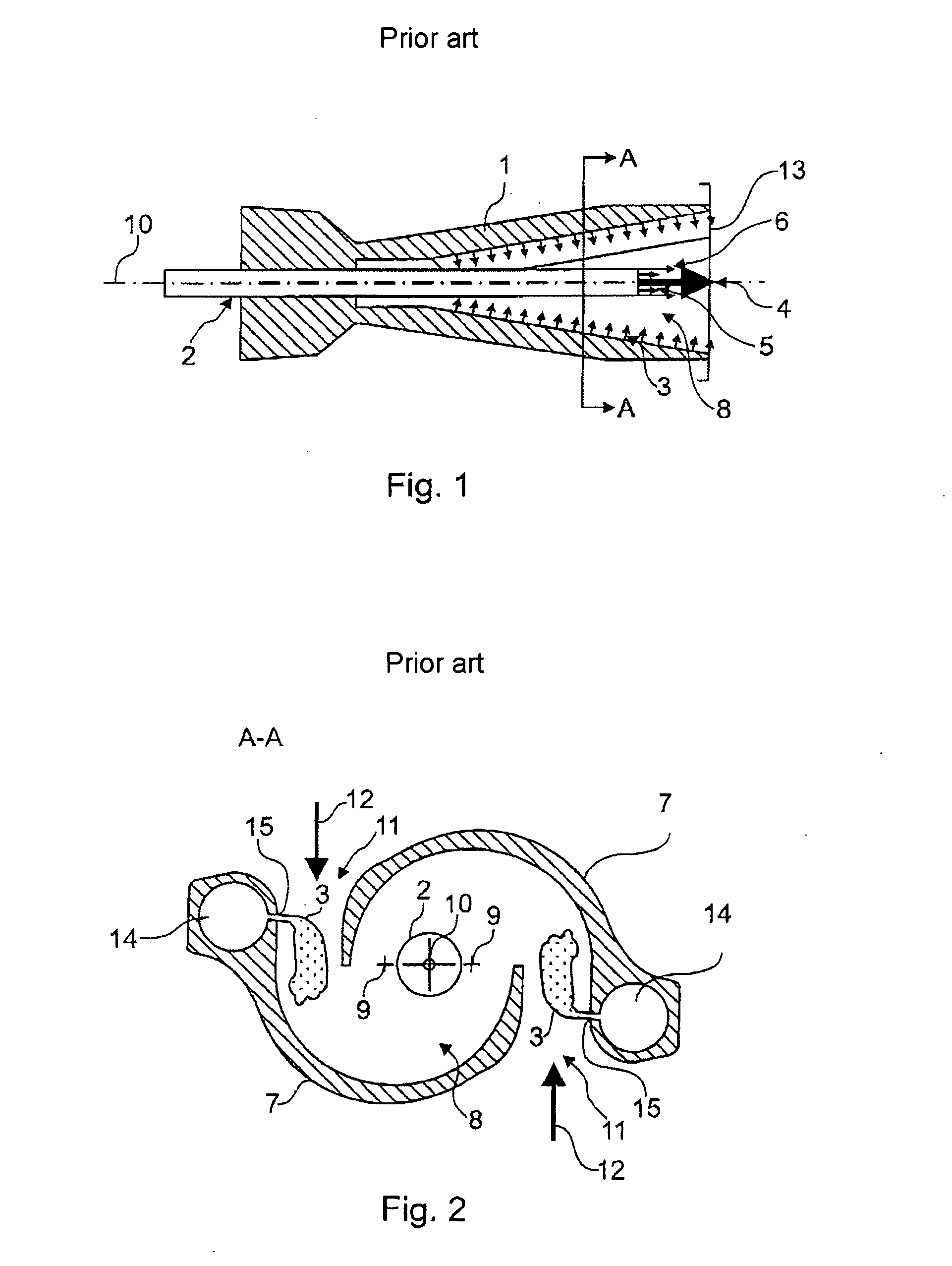
[0043]FIG. 1 shows a longitudinal cross section of a conical burner 1 according to the prior art, as described in EP 0 321 809 A1, for example. In this connection, FIG. 2 shows a cross section along the line A-A of the burner illustrated in FIG. 1. Reference is made below to the numbers of both FIG. 1 and FIG. 2.
[0044] The cone cavity 8 of the burner 1 is formed by two part cone bodies 7 which are displaced radially in relation to one another. The displacement of the longitudinal axes of symmetry 9 of the part cone bodies 7 forms tangential air inlet slots 11, through which the combustion air 12 mixed with premix fuel 3 flows into the cone cavity 8. The burner axis 10 lies centrally and on a line between the longitudinal axes of symmetry 9 of the part cone bodies 7. A jet pipe 2 is provided in the region of this burner axis 10 in order to inject liquid fuel 4 into the combustion space 8. In addition, pilot fuel 6 is introduced into the cone cavity, for initiating or stabilizing the...
PUM
 Abstract
Description
Claims
Application Information