
Systems and methods for monitoring and storing performance and maintenance data related to an electrical component

Inactive Publication Date: 2007-02-01
BATTERY DYNAMICS GROUP
View PDF13 Cites 33 Cited by
  • Summary
  • Abstract
  • Description
  • Claims
  • Application Information

AI Technical Summary

Benefits of technology

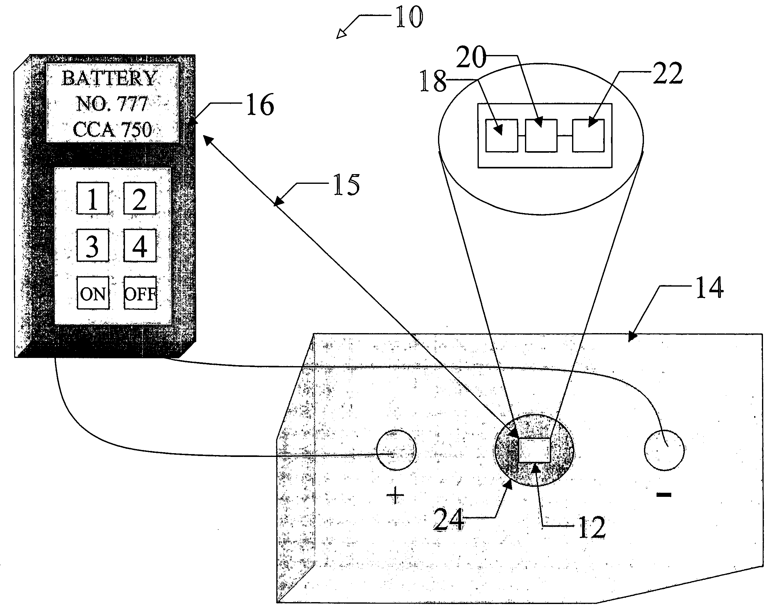
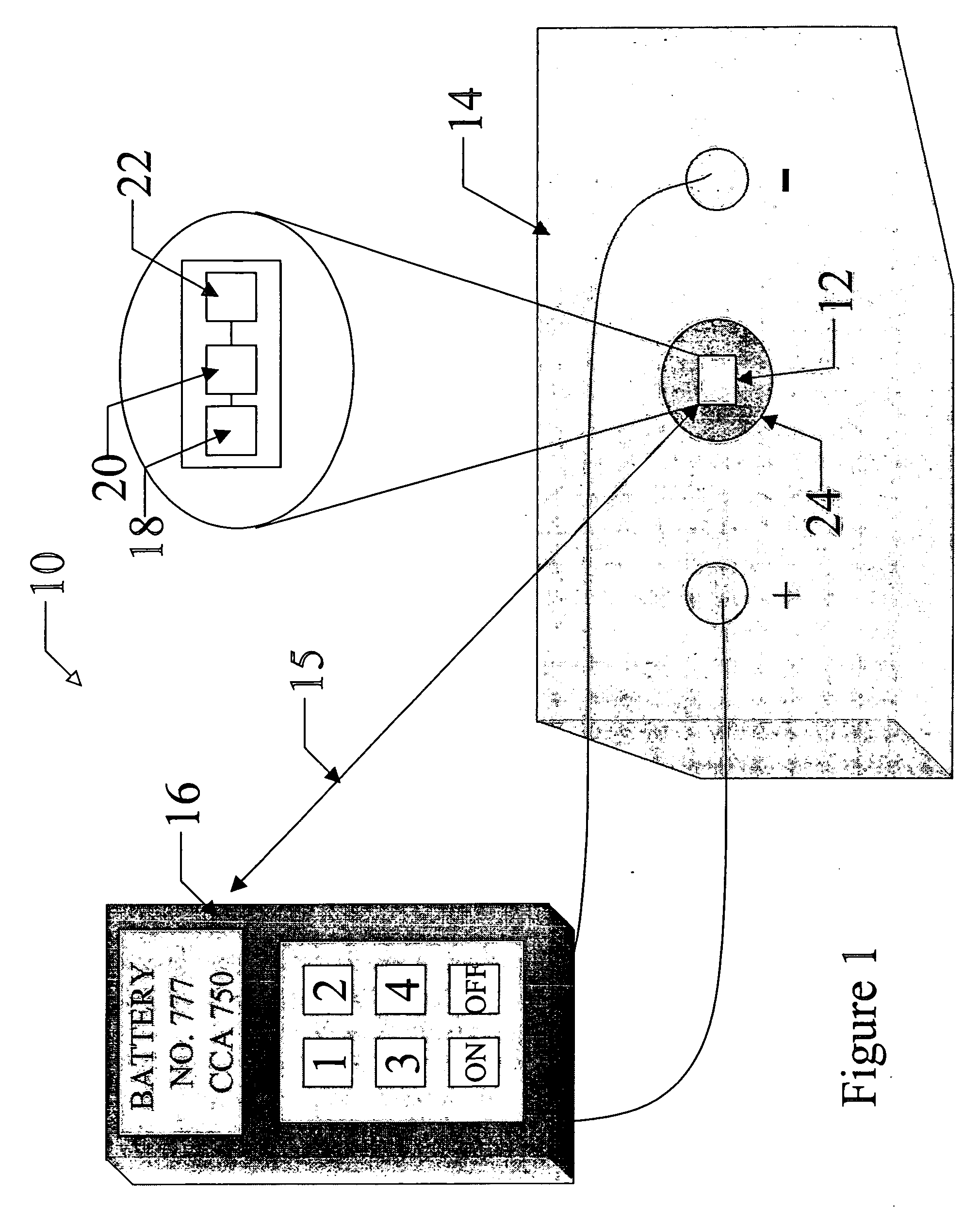
[0025] As mentioned above, the data collection device is typically connected to or incorporated into the component under test. In some embodiments, it is advantageous that the data collection device is connected to the external portion of the component, such that it can be applied to the component after manufacture without requiring the manufacturer to reconfigure their designs. Further, an external data collection device can be placed on existing components as an easy retrofit.
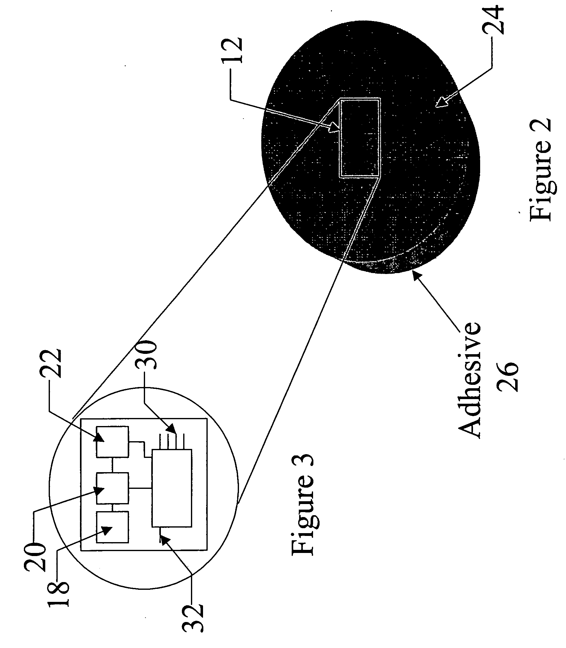
[0026] Although advantageous, placement of the data collection device and other electronics on the external portion of the component under test subjects the data collection device and electronics to several environmental factors that could damage them. For this reason, in one embodiment, the data collection device and associated electronics are surrounded or encased in a rugged housing to protect them from damage. For example, in one embodiment, the data collection device and associated electronics are surrounded or encased in plastic having an adhesive applied to one surface of the encasement for connection to the component under surveillance.
[0027] In addition to ensuring that the data collection device and electronics are not exposed to environmental elements, it is also important to ensure that the data collection device and electronics housed in the encasement are not accidentally dislodged from the component. As such, in one embodiment of the present invention, the data collection device and associated electronics may be surrounded or encased in plastic formed into a circular disc, sometimes referred to as a “poker chip” configuration. This form of encasement is advantageous, as the encasement does not have corners that may be snagged by debris and other items that may dislodge the encasement from the outer surface of the battery or alternator.
[0030] In other embodiments, the data collection device may be an integrated system that includes both a test device and memory device packaged into one system for both performing test and maintenance on the battery and logging the data. For example, the data collection device may include a current, sensor such as a Hall effect sensor that senses current output of the battery. This data is then stored in the memory device, where it is logged and can be later retrieved by a local processor or other device for processing. In this way, each of the batteries can be individually tested and evaluated to determine which of the batteries is malfunctioning. The data collection devices of these embodiments may operate in a continuous or periodic manner so as to collect data on the battery during its normal operation.

Problems solved by technology

Although a regular maintenance schedule can aid in determining problems with the electrical systems, there are some problems with current maintenance practices.
As such, there is added time associated with the maintenance procedure for data input, and also, the data is not readily available and suffers from possible user errors in entering the data.
Further, the data is not directly linked to the battery or alternator.
Here again, there is time lost in maintenance and also the user may access the wrong information for the battery or alternator.
Many batteries returned to the manufacturer under warranty are malfunctioning not due to manufacturing defects, but instead, due to misuse and / or improper maintenance or charging of the battery.
Further, some warranty claims may be dismissed as user misuse and / or improper maintenance and charging, when in reality there is an actual manufacturing problem with the battery or alternator.
An additional problem is many large vehicles, such as trucks, buses, etc. typically have more than one battery on board to start the engine and provide the electrical requirements for the vehicle.
A noted problem is that all the batteries look alike, the good, bad and the marginal.
This can be costly and time consuming.
In addition, many of these conventional test methods individually test each battery, thereby requiring movement of the cables to each battery for testing.
This again is time consuming and can damage the posts of the batteries.
Another issue is that once a battery begins to malfunction, it can have a detrimental effect on the other batteries in the system causing them to possibly degrade and fail.
As such, if a problem with a battery in a bank of batteries is not identified in a timely manner, additionally batteries may be affected, thereby not only raising cost concerns but also raising environmental concerns associated with disposal of malfunctioning batteries.
Further, because the batteries are removed for testing, the batteries are not tested during the normal operational environment.
Again, there may also be errors by maintenance personnel in reading and recording these parameters.

Method used


Image

  • Systems and methods for monitoring and storing performance and maintenance data related to an electrical component
  • Systems and methods for monitoring and storing performance and maintenance data related to an electrical component
  • Systems and methods for monitoring and storing performance and maintenance data related to an electrical component

Examples


Embodiment Construction

[0039] The present inventions now will be described more fully hereinafter with reference to the accompanying drawings, in which some, but not all embodiments of the invention are shown. Indeed, these inventions may be embodied in many different forms and should not be construed as limited to the embodiments set forth herein; rather, these embodiments are provided so that this disclosure will satisfy applicable legal requirements. Like numbers refer to like elements throughout.

[0040] As mentioned above and provided in more detail below, the present invention provides systems and methods for collecting, logging, and analyzing test and maintenance data for a component. Importantly, the systems and methods of the present invention include a data collection device that is associated and / or connected to the component. Each time the component is tested or maintenance is performed thereon, the data concerning the tests and maintenance is stored in the data collection device. As such, the ...


PUM


Abstract

The present invention provides systems and methods for testing and storage of information related to a component. A data collection device having a memory is fixedly connected to the component. A test device communicates with the data collection device to store test data concerning the component in the data collection device. The test device also performs analysis of the test data and provides information concerning the health and maintenance history of the component. The present invention also provides systems and methods for determining the current drawn or supplied by electrical components connected in parallel in an electrical system. A current sensor located between the electrical components determines the current supply or draw of one of the electrical components, while a current sensor between the electrical components and the remainder of the electrical system determine a cumulative current draw or supply by both the electrical components.

Description

CROSS-REFERENCE TO RELATED APPLICATIONS [0001] The present application claims priority from U.S. Provisional Application Ser. No. 60 / 310,716 entitled SYSTEMS AND METHODS FOR MONITORING AND STORING VEHICLE CHARGING SYSTEM DATA, filed Aug. 7, 2001, the contents of which are incorporated herein by reference.BACKGROUND OF THE INVENTION [0002] 1. Field of the Invention [0003] This invention relates to test and diagnostic equipment used to gather and store performance and maintenance data related to a component. [0004] 2. Description of Related Art [0005] An important concern associated with the maintenance of any vehicle is the status of the vehicle's electrical system. As the battery and alternator of a vehicle are essential to the cranking and normal operation of the vehicle, it is important that they are properly and frequently tested, to ensure that they are operating correctly. For this reason, many fleet and vehicle and equipment rental companies perform routine testing and mainten...

Claims


Application Information

Patent Timeline
IPC IPC(8): G01R21/06G01R21/00G01R31/00G01R31/36H01M10/44H01M10/48H01M50/569
CPCG01R31/006G01R31/007G01R31/3606G01R31/3648H01M10/482G01R31/3679G01R31/3693H01M10/441G01R31/3675G01R31/374G01R31/382G01R31/392G01R31/3647Y02E60/10H01M50/569
Inventor LESESKY, ALAN C.PURKEY, BRUCE A.WEANT, BOBBY RAY
Owner BATTERY DYNAMICS GROUP
Learn More