Induction plasma synthesis of nanopowders

a nanopowder and plasma technology, applied in the field of induction plasma synthesis of nanopowders, can solve the problems of the temperature of the condensation surface changes with the build-up of the condensed nanopowder layer, and the use of a cooling surface suffers from the drawback of particle build-up on the condensation surface, so as to achieve excellent control of the morphology and particle size distribution of the resulting nanop

Active Publication Date: 2007-02-08
TEKNA PLASMA SYST INC
View PDF10 Cites 60 Cited by
  • Summary
  • Abstract
  • Description
  • Claims
  • Application Information

AI Technical Summary

Benefits of technology

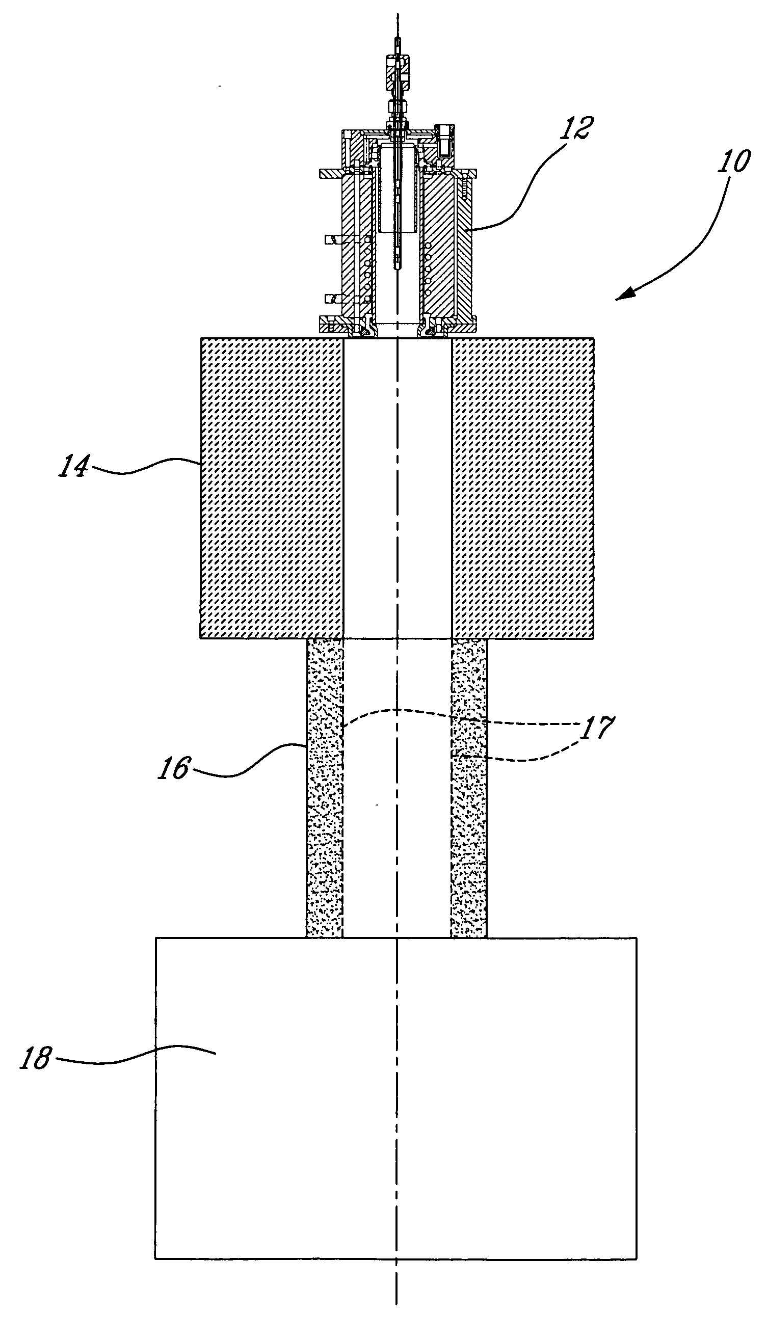
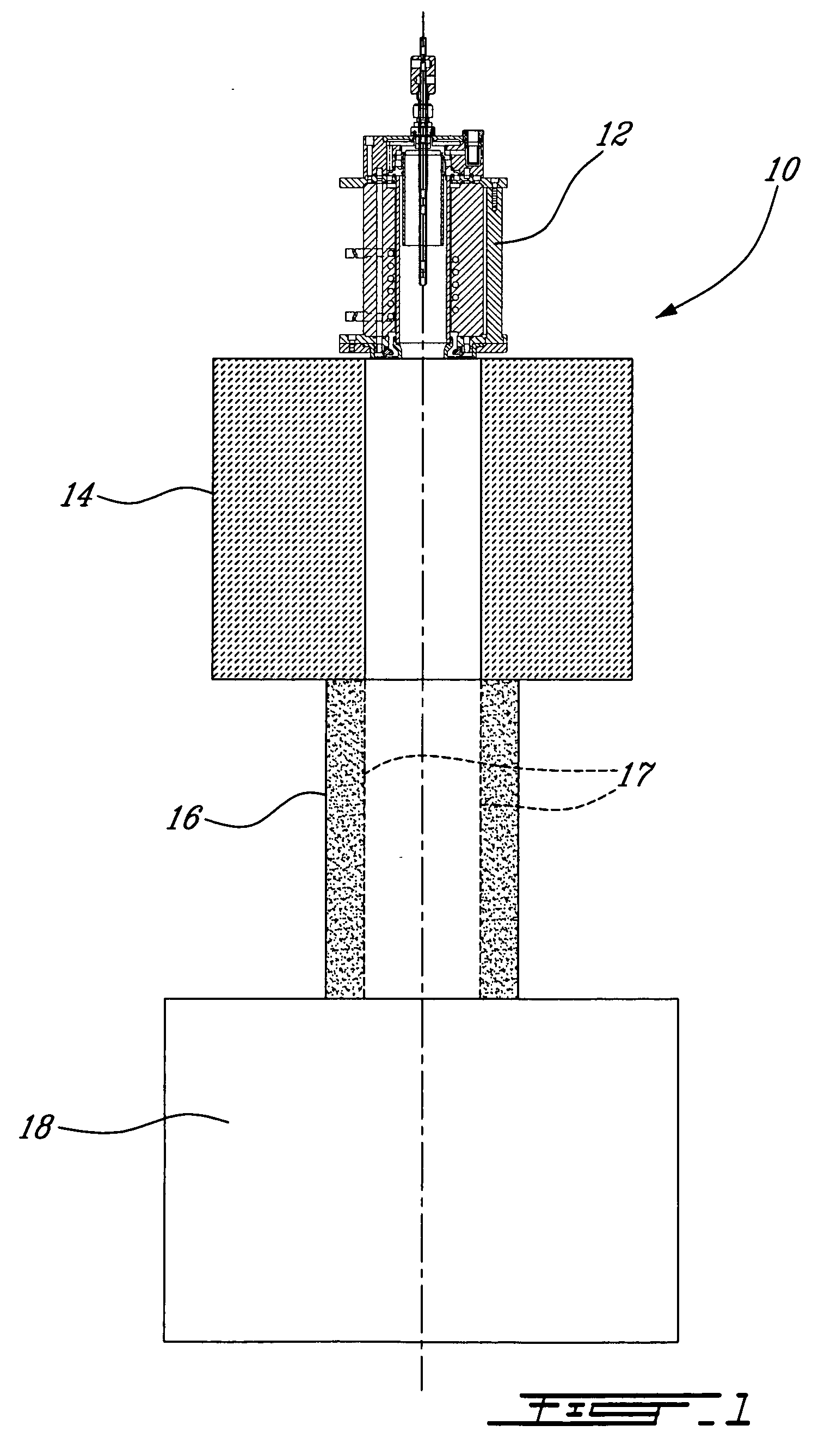
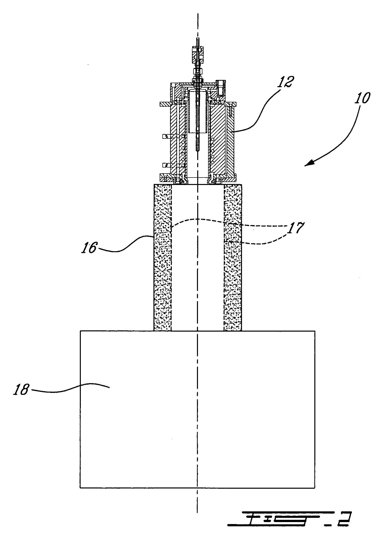
[0010] The present invention relates to the plasma synthesis of powders calling upon an induction plasma apparatus comprising an induction plasma torch and a quenching chamber in which a renewable “gaseous cold front” is generated, through the injection of a quench gas, and on which the gaseous reactants / reaction products nucleate. The nucleation generates a nanopowder which is rapidly transported to a collection chamber by the moving cold front. It was surprisingly discovered that by generating a renewable gaseous cold front for nucleating (i.e. condensing) the reactants / reaction products present in the plasma flow, excellent control of the morphology and particle size distribution of the resulting nanopowder could be achieved. Moreover, the use of the renewable gaseous cold front offers a close control over particle agglomeration.

Problems solved by technology

However, a drawback of the use of traditional “cold-surface” condensation techniques is that the nature and the temperature of the condensation surface changes with the build-up of the condensed nanopowder layer.
The use of a cooling surface suffers from the drawback of particle build-up on the condensation surface.
69. However, these references remain silent as to an efficient method for producing nanopowders of well defined particle size distribution and morphol

Method used


Image

  • Induction plasma synthesis of nanopowders
  • Induction plasma synthesis of nanopowders
  • Induction plasma synthesis of nanopowders

Examples


Embodiment Construction

[0030] In order to provide a clear and consistent understanding of the terms used in the present specification, a number of definitions are provided below. Moreover, unless defined otherwise, all technical and scientific terms as used herein have the same meaning as commonly understood to one of ordinary skill in the art to which this invention pertains.

[0031] The use of the word “a” or “an” when used in conjunction with the term “comprising” in the claims and / or the specification may mean “one”, but it is also consistent with the meaning of“one or more”, “at least one”, and “one or more than one”. Similarly, the word “another” may mean at least a second or more.

[0032] As used in this specification and claim(s), the words “comprising” (and any form of comprising, such as “comprise” and “comprises”), “having” (and any form of having, such as “have” and “has”), “including” (and any form of including, such as “include” and “includes”) or “containing” (and any form of containing, such...


PUM

PropertyMeasurementUnit
pressureaaaaaaaaaa
Plasma poweraaaaaaaaaa
pressureaaaaaaaaaa

Abstract

A process and apparatus for synthesizing a nanopowder is presented. In particular, a process for the synthesis of nanopowders of various materials such as metals, alloys, ceramics and composites by induction plasma technology, using organometallic compounds, chlorides, bromides, fluorides, iodides, nitrites, nitrates, oxalates and carbonates as precursors is disclosed. The process comprises feeding a reactant material into a plasma torch in which is generated a plasma flow having a temperature sufficiently high to yield a superheated vapour of the material; transporting said vapour by means of the plasma flow into a quenching zone; injecting a cold quench gas into the plasma flow in the quenching zone to form a renewable gaseous cold front; and forming a nanopowder at the interface between the renewable gaseous cold front and the plasma flow.

Description

CROSS REFERENCE TO RELATED APPLICATIONS [0001] This application claims the benefit of U.S. Provisional Application No. 60 / 647,427, filed Jan. 28, 2005, which is incorporated by reference.FIELD OF THE INVENTION [0002] The present invention relates to the plasma synthesis of nanopowders using induction plasma technology. More specifically, but not exclusively, the present invention relates to a process for the synthesis of nanopowders of various materials such as metals, alloys, ceramics and composites by induction plasma technology, using organometallic compounds, chlorides, bromides, fluorides, iodides, nitrites, nitrates, oxalates and carbonates as precursors. BACKGROUND OF THE INVENTION [0003] The plasma synthesis of nanopowders has attracted increasing attention over the past few years. Numerous processes have been developed for preparing metal, alloy and ceramic-based nanopowders using a wide variety of technologies including plasma discharge, arc discharge, electro-explosion, s...

Claims


Application Information

Patent Timeline
Patent Type & Authority Applications(United States)
IPC IPC(8): B23K9/00B23K9/02
CPCB01J19/088B01J2219/0871H05H1/30C01P2006/12B01J2219/0875B01J2219/0877B01J2219/0879B01J2219/0894B22F9/12B22F2999/00B82Y30/00C01B13/30C01B31/36C01G1/00C01G1/02C01G17/02C01P2004/64B22F2202/13C01B32/991B82B3/00B82Y40/00
Inventor BOULOS, MAHER I.JUREWICZ, JERZYGUO, JIAYIN
Owner TEKNA PLASMA SYST INC
Why Eureka
Try Eureka