
Time-of-flight mass spectrometer combining fields non-linear in time and space

a mass spectrometer and time-of-flight technology, applied in the field of mass spectrometers, can solve the problems of reducing the resolution power, creating a distinct detrimental effect known as the turn-around time, and little time available for mass separation

Inactive Publication Date: 2007-02-08
THE JOHN HOPKINS UNIV SCHOOL OF MEDICINE
View PDF6 Cites 11 Cited by
  • Summary
  • Abstract
  • Description
  • Claims
  • Application Information

AI Technical Summary

Benefits of technology

[0043] In another embodiment, the ion source further provides a delay pulse to allow for the dissipation of neutral molecules and free-radical chemical species. The ion source can also further provide a short-duration, high-amplitude voltage pulse prior to ion ejection from the source in order to bias an initial energy distribution of an ion population.

Problems solved by technology

However, any one of these conditions is rarely achieved and the resolving power is consequently diminished.
The energy effect also creates a distinct detrimental effect known as the turn-around time, whereby those ions having a thermal energy vector directed against the accelerating field travel away from the ion source exit before being turned around.
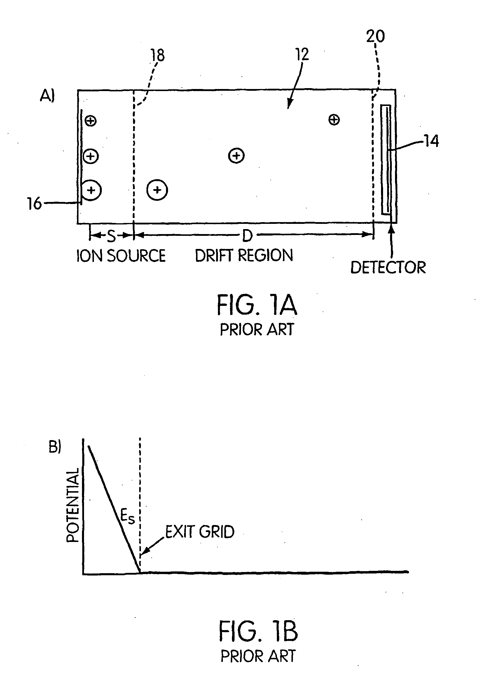
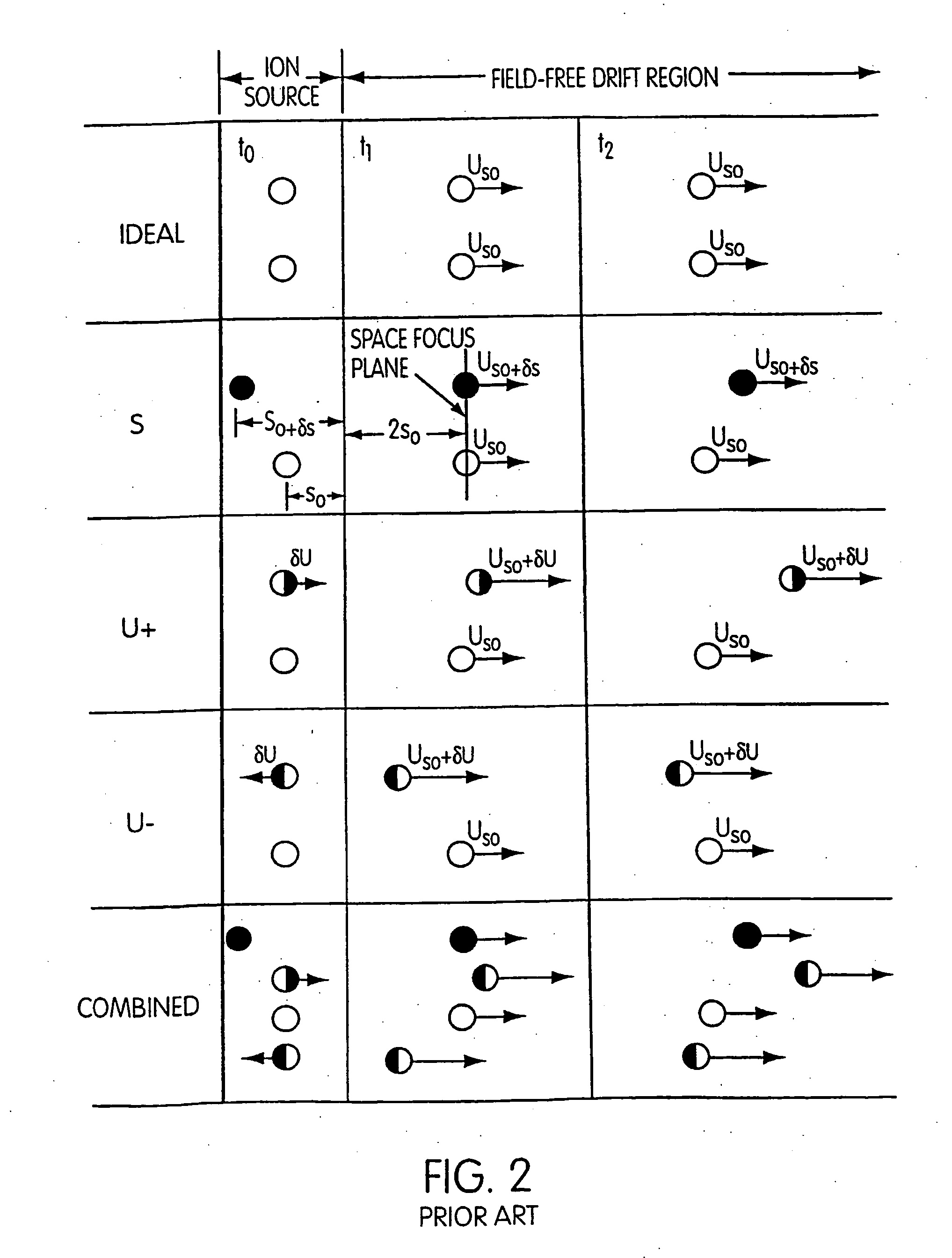
However, this required an axially short ion source geometry and, as the detector must consequently be placed only a short distance (2s0) from the ion source in order to achieve a space focus condition, little time was available for mass separation.
However, the optimal time lag is mass dependent, limiting the m / z range that could be simultaneously measured.
While all ions leave the mirror having exactly the same magnitude of energy with which they entered, those ions possessing the greater energy travel farther into the mirror before being repelled and thus experience a time delay that compensates for their higher velocity in the field-free region.
However, for applications having a relatively large initial ion energy distribution, the achievable resolving power is diminished.
However, this still does not overcome the spatial problem, and for some methods where the ionization process occurs within the source, a large initial ion energy distribution may inherent to the analysis.
Each of these designs provides only minor improvement to the resolving power achieved using linear-field ion mirrors, and each is suitable to only a relatively narrow initial range of ion energies.
While non-linear fields are theoretically preferable to linear fields, one of the practical drawbacks to generating such fields in ion mirrors is the result of their inherent radial field-inhomogeneity.
An ion beam of finite diameter will thus experience a range of non-linear fields, which reduces the resultant resolving power and radially disperses the ion beam, diminishing the ion transmission.
However, those ions farthest from the detector in a given isomass packet experience a greater increase in energy, allowing them to catch up to those ions closer to the detector, and thus decrease the temporal distribution of the ion packet.
However, such devices cannot completely eliminate the distribution due to the fact that some ions in the initial ion population have positive initial energy vectors while others have negative initial energy vectors (i.e. the turn-around effect).
However, for ion populations possessing both positive and negative vectors, complete energy focusing is not possible.
However, this was proposed for the limited analysis of MALDI-generated ions and has not been thoroughly developed.
It also does not account for a static non-linear-field ion source.

Method used


Image

  • Time-of-flight mass spectrometer combining fields non-linear in time and space
  • Time-of-flight mass spectrometer combining fields non-linear in time and space
  • Time-of-flight mass spectrometer combining fields non-linear in time and space

Examples


Embodiment Construction

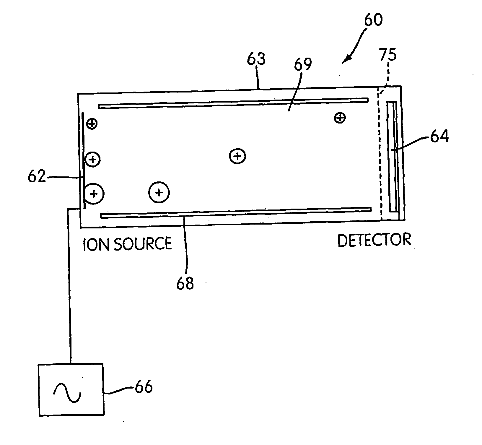
[0061] One aspect of the present invention is to provide a time-of-flight mass spectrometer that uses a combination of static and dynamic non-linear electric fields (that is, electric fields that are non-linear in both space and time) to achieve the best resolving power in the analysis of any initial 3-dimensional gas-phase ion population.

[0062] In one embodiment shown in FIG. 6, the mass spectrometer 60 includes ion source 62, an evacuated tube 63 proximate the ion source 62 and adapted to receive ions from the ion source. The mass spectrometer 60 also includes detector 64 disposed at an end of the evacuated tube 63 opposite an end proximate the ion source 62.

[0063] The ion source 62 includes sample holder or sample probe for holding a sample to be mass analyzed. The ion source 62 also comprises a voltage source 66 that can be modulated in time to generate an electric field that can change as a function of time.

[0064] The ions are formed and accelerated by an electric field defi...


PUM


Abstract

A time-of-flight mass spectrometer which has an iron source, an evacuated tube proximate the ion source and adapted to receive ions from the ion source, and a detector disposed at an end of the evacuated tube opposite an end proximate the ion source. The ion source is constructed to generate an electric field that changes non-linearly as a function of position along a path from the ion source to the detector. The ion source is constructed to generate an electric field that changes as a function of time, the electric field being provided to accelerate ions from the ion source to the detector.

Description

PRIOR PROVISIONAL APPLICATION INFORMATION [0001] This Application is based on Provisional Application No. 60 / 384,344 filed May 30, 2002, the entire contents of which is hereby incorporated by reference.STATEMENT AS TO RIGHTS TO INVENTIONS MADE UNDER FEDERALLY SPONSORED RESEARCH AND DEVELOPMENT [0002] The present invention was conceived during the course of work supported by grant No. GM64402 from the National Institutes of Health and DARPA grants NDCH102007 and DABT63-99-1-0006.BACKGROUND OF THE INVENTION [0003] 1. Field of Invention [0004] The present invention relates to a mass spectrometer in general and in particular to a mass spectrometer that employs ion focusing fields which are non-linear in both space and time to improve mass resolution. [0005] 2. Description of Related Art [0006] Mass spectrometers are instruments that are used to determine the chemical composition of substances and the structures of molecules. In general they consist of an ion source where neutral molecul...

Claims


Application Information

Patent Timeline
Patent Type & Authority Applications(United States)
IPC IPC(8): H01J49/00
CPCH01J49/40H01J49/10
Inventor COTTER, ROBERT JAMESGARDNER, BENJAMIN D.HOLLAND, JOHN F.
Owner THE JOHN HOPKINS UNIV SCHOOL OF MEDICINE
Learn More