Supercharge Your Innovation With Domain-Expert AI Agents!

Test circuit with drive windings and sense elements

a test circuit and drive winding technology, applied in the field of non-destructive materials characterization, can solve the problems of small separation between the layers and the change in the response of the sense element, and achieve the effect of reducing the cost and complexity of manufacturing

Inactive Publication Date: 2007-02-08
JENTEK SENSORS
View PDF12 Cites 8 Cited by
  • Summary
  • Abstract
  • Description
  • Claims
  • Application Information

AI Technical Summary

Benefits of technology

[0007] A planar test circuit may comprise a drive winding, the drive winding comprising one or more planar electrical conductors deposited on a substrate for imposing a field in a test material when driven by an electrical current, all of the electrical current flowing in one direction about an axis. The test circuit further comprises at least two planar sense elements proximate to and spaced along the electrical conductors of the drive winding for sensing the response of the test material to the imposed field. Leads connect to each sense element. An inner drive winding loop may, for example, be placed in a layer with the sense elements and not in the same layer as an outer drive winding loop. Each winding may further comprise a single conductive layer on a substrate in a substantially planar structure. However, the separation between these layers is relatively small compared to the thickness of typical drive coils. The planar structure of the test circuit reduces the cost and complexity of manufacturing and provides a low mass circuit, the response of which can be modeled.

Problems solved by technology

Any flaws or cracks will interrupt the flow of induced eddy currents and lead to a change in the sense element response.
However, the separation between these layers is relatively small compared to the thickness of typical drive coils.

Method used


Image

  • Test circuit with drive windings and sense elements
  • Test circuit with drive windings and sense elements
  • Test circuit with drive windings and sense elements

Examples


Embodiment Construction

[0033] A description of preferred embodiments of the invention follows.

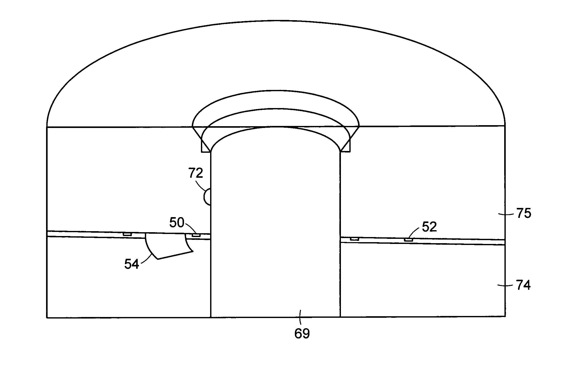
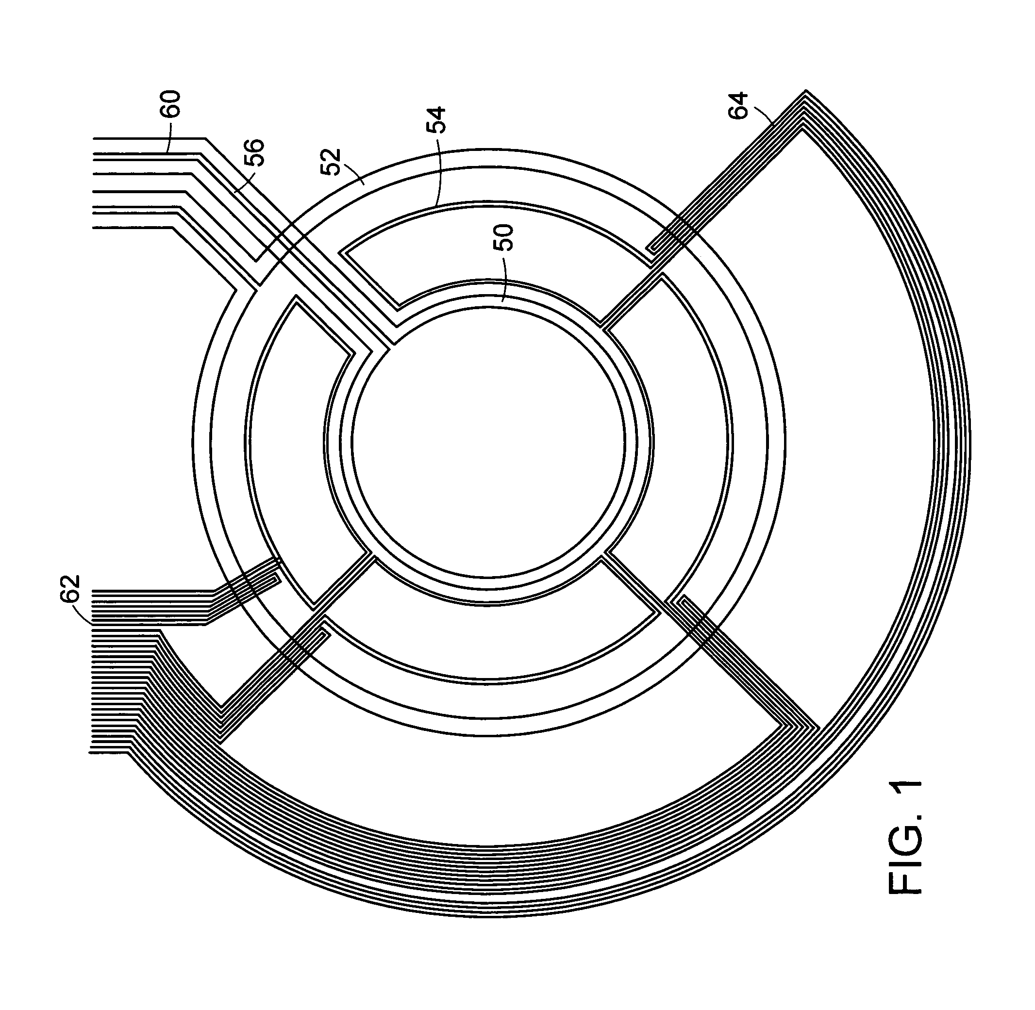
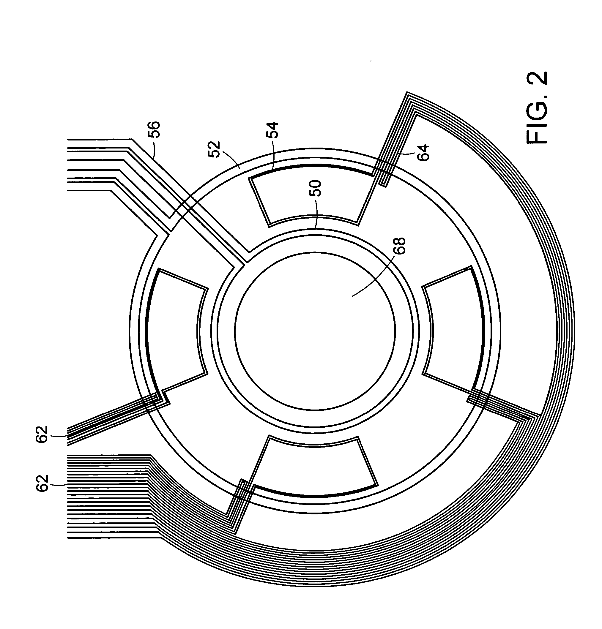
[0034] The design and use of conformable eddy current sensor arrays are described for the nondestructive characterization of materials in the vicinity of and around features in the materials, such as holes or fasteners. For circular features, this is accomplished with circular magnetic field sensor arrays. Often the geometry changes and any material property (e.g., electrical conductivity and / or magnetic permeability) differences between the feature and the surrounding material can mask the presence of flaws or defects. An example is a fastener for joining material layers, such as a magnetizable steel fastener joining aluminum or titanium alloy layers, where the geometric and material property differences can dominate the sensor response signals and mask the response signals from hidden cracks located beneath the head of the fastener. However, the sensors can be designed to match the symmetry of the test materia...


PUM

PropertyMeasurementUnit
frequencyaaaaaaaaaa
frequencyaaaaaaaaaa
frequencyaaaaaaaaaa

Abstract

Magnetic field based eddy-current sensing arrays measure the near surface properties conducting and magnetic materials. The arrays have a drive winding for imposing the magnetic field in a test material and at least two sense elements for sensing the response of the test material to the magnetic field. Each sense element has distinct leads for connection to impedance measurement instrumentation. The arrays have accurately positioned sense elements and drive winding conductors so that the sense element responses are essentially identical for test materials having uniform properties. The drive windings are typically formed into circular loops for examining material properties in the vicinity of circular features in the test material, such as holes or fasteners. For examining the material, the sensor arrays are rotated around the feature or mounted against a material surface and provide information from multiple locations around the feature to determine if cracks are present or to monitor crack growth.

Description

RELATED APPLICATION(S) [0001] This application claims the benefit of U.S. Provisional Application No. 60 / 676,786, filed on May 2, 2005. The entire teachings of the above applications are incorporated herein by reference.BACKGROUND OF THE INVENTION [0002] The technical field of this invention is that of nondestructive materials characterization, particularly quantitative, model-based characterization of surface, near-surface, and bulk material condition for flat and curved parts or components. Characterization of bulk material condition includes (1) measurement of changes in material state, i.e., degradation / damage caused by fatigue damage, creep damage, thermal exposure, or plastic deformation; (2) assessment of residual stresses and applied loads; and (3) assessment of processing-related conditions, for example from aggressive grinding, shot peening, roll burnishing, thermal-spray coating, welding or heat treatment. It also includes measurements characterizing the material, such as...

Claims


Application Information

Patent Timeline
Patent Type & Authority Applications(United States)
IPC IPC(8): G01N27/82
CPCG01N27/9046
Inventor GOLDFINE, NEIL J.SCHLICKER, DARRELL E.WALRATH, KAREN E.WASHABAUGH, ANDREW P.GRUNDY, DAVID C.
Owner JENTEK SENSORS
Features
  • R&D
  • Intellectual Property
  • Life Sciences
  • Materials
  • Tech Scout
  • Unparalleled Data Quality
  • Higher Quality Content
  • 60% Fewer Hallucinations
Learn More