Optical interrogation system and method for increasing a read-out speed of a spectrometer

Inactive Publication Date: 2007-02-08
CORNING INC
View PDF19 Cites 26 Cited by
  • Summary
  • Abstract
  • Description
  • Claims
  • Application Information

AI Technical Summary

Problems solved by technology

Unfortunately, such a receive system and in particular its CCD detector, which is used in industry today, may easily be saturated by the received light.
Such, CCD detector saturation makes it difficult to detect minute shifts (e.g., sub-picometer wavelength shifts) in the optical response, which means it becomes difficult

Method used


Image

  • Optical interrogation system and method for increasing a read-out speed of a spectrometer
  • Optical interrogation system and method for increasing a read-out speed of a spectrometer
  • Optical interrogation system and method for increasing a read-out speed of a spectrometer

Examples


Example

DETAILED DESCRIPTION OF THE DRAWINGS

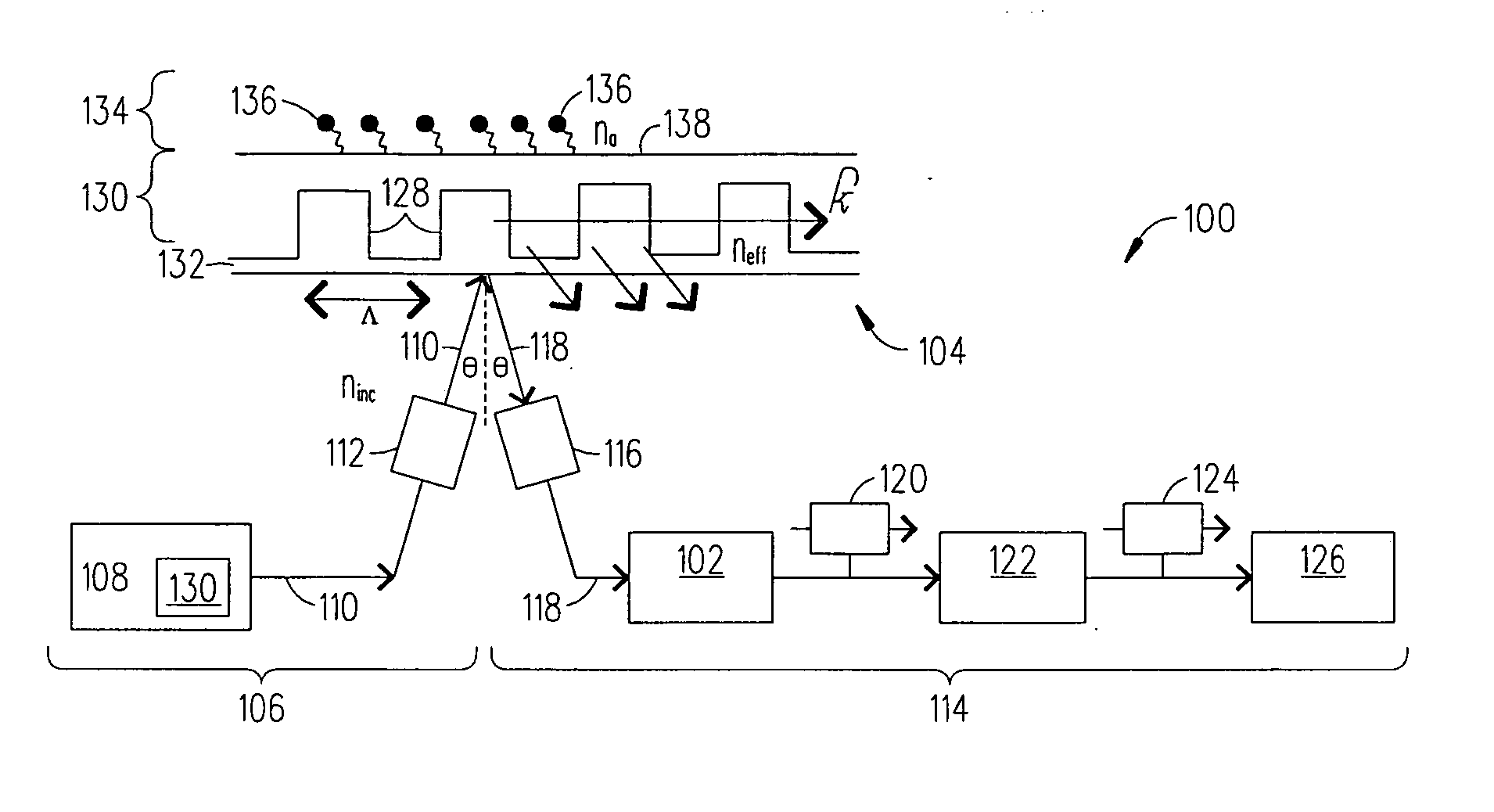
[0016] Referring to FIG. 1, there is a block diagram of an exemplary optical interrogation system 100 (incorporating an enhanced spectrometer 102) which is used to interrogate a biosensor 104 (e.g., RWG biosensor 104) in accordance with the present invention. The optical interrogation system 100 includes a launch system 106 which has a light source 108 that outputs an optical beam 110 into a lensed fiber optic 112 which emits the optical beam 110 towards RWG biosensor 104. In addition, the optical interrogation system 100 includes a receive system 114 which has a lensed fiber optic 116 that receives an optical beam 118 reflected / out-coupled from the RWG biosensor 104. The receive system 114 also includes a spectrometer / detector array 102 (enhanced in accordance with the present invention) which receives the optical beam 118 emitted from the lensed fiber optic 116. The enhanced spectrometer 102 outputs a voltage signal 120 (representative of the r...


PUM


Abstract

A typical use of linear or two dimensional spectrometers is to expose the detector area, and then shift the photo-electric charges out of the device in a serial fashion. If the illuminating signal is spatially narrow relative to the size of the array, this will drive down the percent of the detector that is utilized, as only a relatively small number of pixels are used to detect the beam. The present invention proposes a method which capitalizes on this spatial under-utilization, and alters the clocking scheme to maximize the read-out speed of the pixels containing signal information. This type of clocking scheme raises the optical power saturation level of the spectrometer. Such an improvement in optical power handling is beneficial for spectrometer based detection of resonant waveguide grating biochemical binding, since in such systems the performance is frequently limited by spectrometer saturation.

Description

CLAIMING BENEFIT OF PROVISIONAL APPLICATION [0001] This application claims the benefit of U.S. Provisional Application Ser. No. 60 / 706,832 filed on Aug. 8, 2005, the contents of which are incorporated by reference herein.BACKGROUND OF THE INVENTION [0002] 1. Field of the Invention [0003] The present invention relates to an optical interrogation system which implements an over-clocking method that increases a read-out speed of a CCD (charge coupled device) detector (in this case part of a spectrometer) which enhances the ability to detect a minute / small biological event on or near a top surface of an optical biosensor. [0004] 2. Description of Related Art [0005] Today optical sensor technology is being used in academia and industry to conduct studies associated with detecting a biological event on or near a top surface of an optical biosensor. In such studies, an optical interrogation system is used which has a launch system that couples light into an optical biosensor (e.g., resonan...

Claims


Application Information

Patent Timeline
IPC IPC(8): G01N21/00
CPCG01N21/7743G01J3/2803
Inventor PIECH, GARRETT A.WEBB, MICHAEL B.
Owner CORNING INC
Why Eureka
Try Eureka