Lithium secondary battery

a secondary battery and negative electrode technology, applied in the manufacture of electrodes, cell components, final product manufacturing, etc., can solve the problems of negative electrode deformation, non-homogeneous charge, and concern for a decline in cycle characteristics, so as to improve cycle characteristics, reduce material losses, and enhance charge and discharge efficiency

Inactive Publication Date: 2007-02-08
PANASONIC CORP
View PDF18 Cites 125 Cited by
  • Summary
  • Abstract
  • Description
  • Claims
  • Application Information

AI Technical Summary

Benefits of technology

[0031] According to the present invention, since the columnar particles forming the negative electrode active material layer are tilted toward the normal direction of the current collector, seeing from the positive electrode side, the exposed part of the negative electrode current collector drastically decreases. Thus, the area where the positive electrode active material and the negative electrode active material are facing becomes large, to cause homogeneous electrode reaction, enhance charge and discharge efficiency, and improve cycle characteristics.
[0032] Additionally, when lithium corresponding to irreversible capacity is supplemented to the negative electrode before forming a battery, residual lithium on the current collector will decrease due to the extremely smaller degree of negative electrode current collector exposure. Thus, while material losses are decreased, side reactions of electrolyte can be suppressed, which enables sustainable, excellent battery performance for a longer period of time. The supplement of lithium corresponding to irreversible capacity can be carried out by attaching lithium metal to the negative electrode, or by vapor-depositing lithium metal on the negative electrode.
[0033] The tilting of the columnar particles toward the normal direction of the current collector is also advantageous for high-rate charge and discharge, since the contact area between the negative electrode active material and the electrolyte will increase.

Problems solved by technology

The problem in using silicon as a negative electrode active material is deformations of the negative electrode.
Thus, a gap is created between the negative electrode and a separator, causing non-homogeneous charge and discharge reactions, leaving a concern for a decline in cycle characteristic.
As a result, lithium cannot be released from the negative electrode effectively at the time of discharging, thereby declining charge and discharge efficiency.
This may cause a partial over-discharge in the positive electrode active material, while declining substantial discharge capacity.
Thus, side reaction increases, discharge capacity decreases, and deterioration of battery advances.
Especially, when a high-rate charge and discharge is carried out at a large current value, cycle characteristics decline drastically.

Method used


Image

  • Lithium secondary battery
  • Lithium secondary battery
  • Lithium secondary battery

Examples


example 1

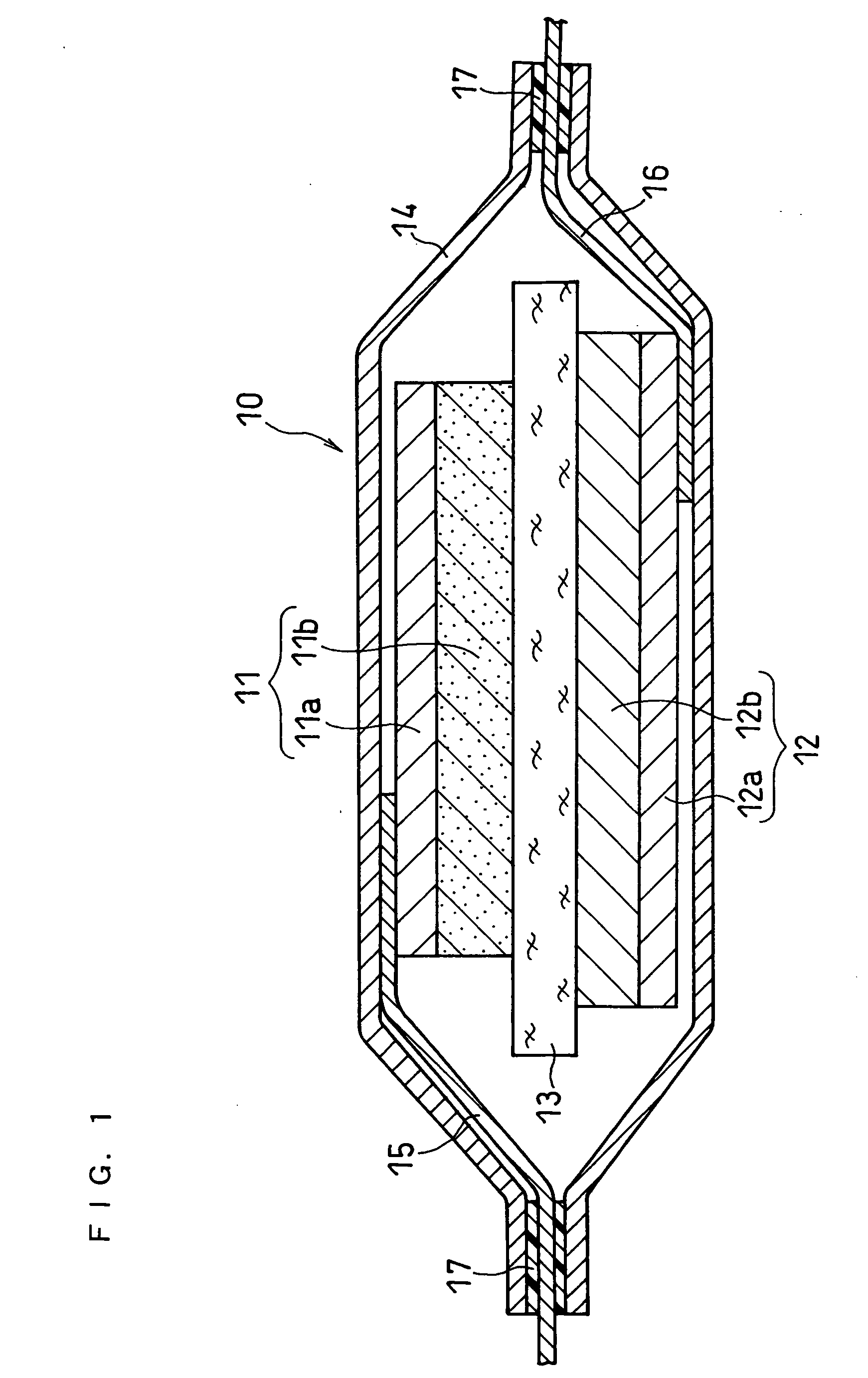
[0073] A laminated lithium secondary battery shown in FIG. 1 was made.

(i) Preparation of Positive Electrode

[0074] A positive electrode material mixture paste was prepared by sufficiently mixing 10 g of lithium cobaltate (LiCoO2) powder with the average particle size of about 10 μm as a positive electrode active material, 0.3 g of acetylene black as a conductive agent, 0.8 g of polyvinylidene fluoride powder as a binder, and an appropriate amount of N-methyl-2-pyrrolidone (NMP). The obtained paste was applied on one side of a positive electrode current collector 11a comprising an aluminum foil with a thickness of 20 μm, dried, and rolled, to form a positive electrode active material layer 11b. Subsequently, a positive electrode was cut out to give a predetermined form. In the obtained positive electrode, the positive electrode active material layer carried on one side of the aluminum foil had a thickness of 50 μm, and a size of 30 mm×30 mm. To the current collector rear side havin...

example 2

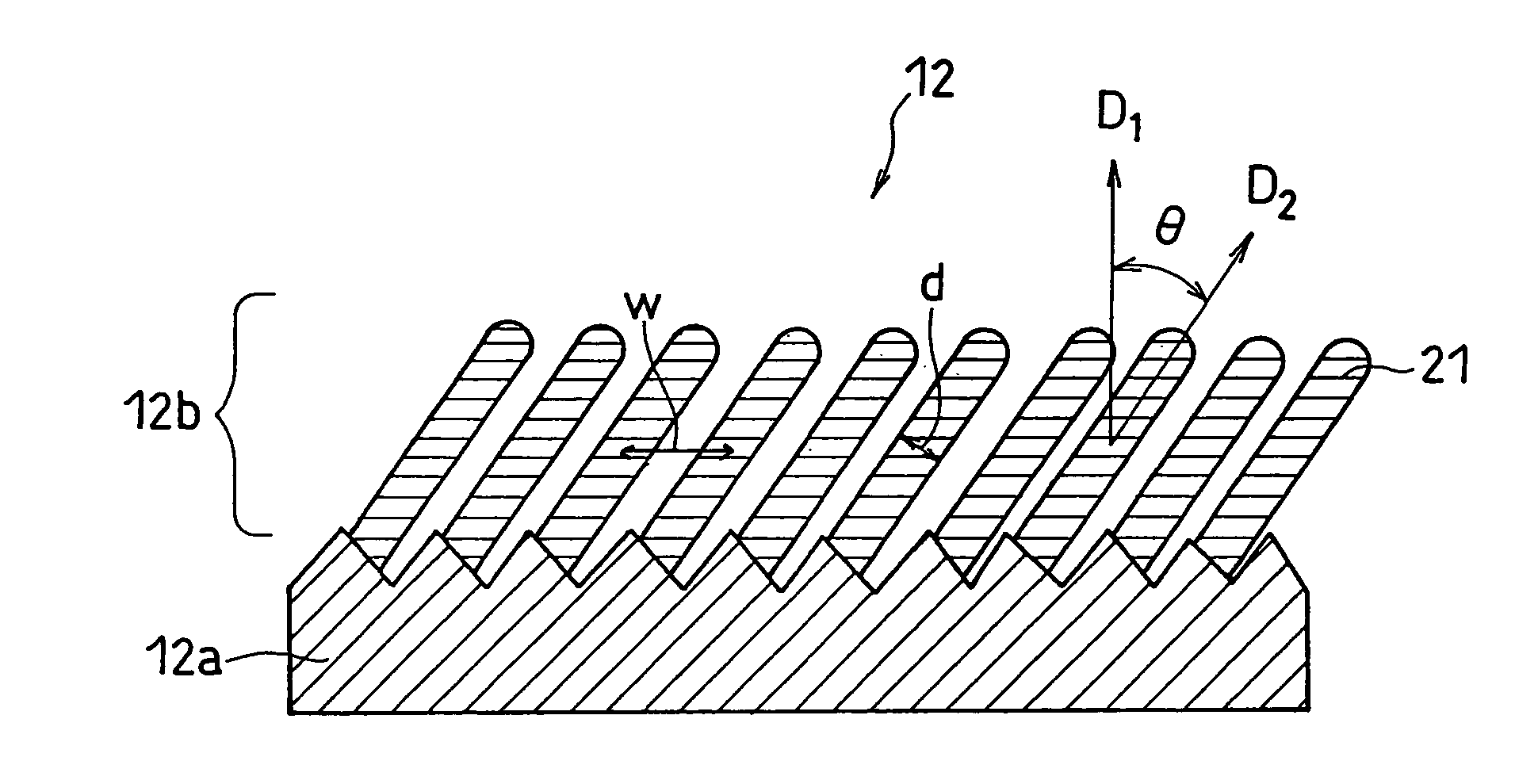
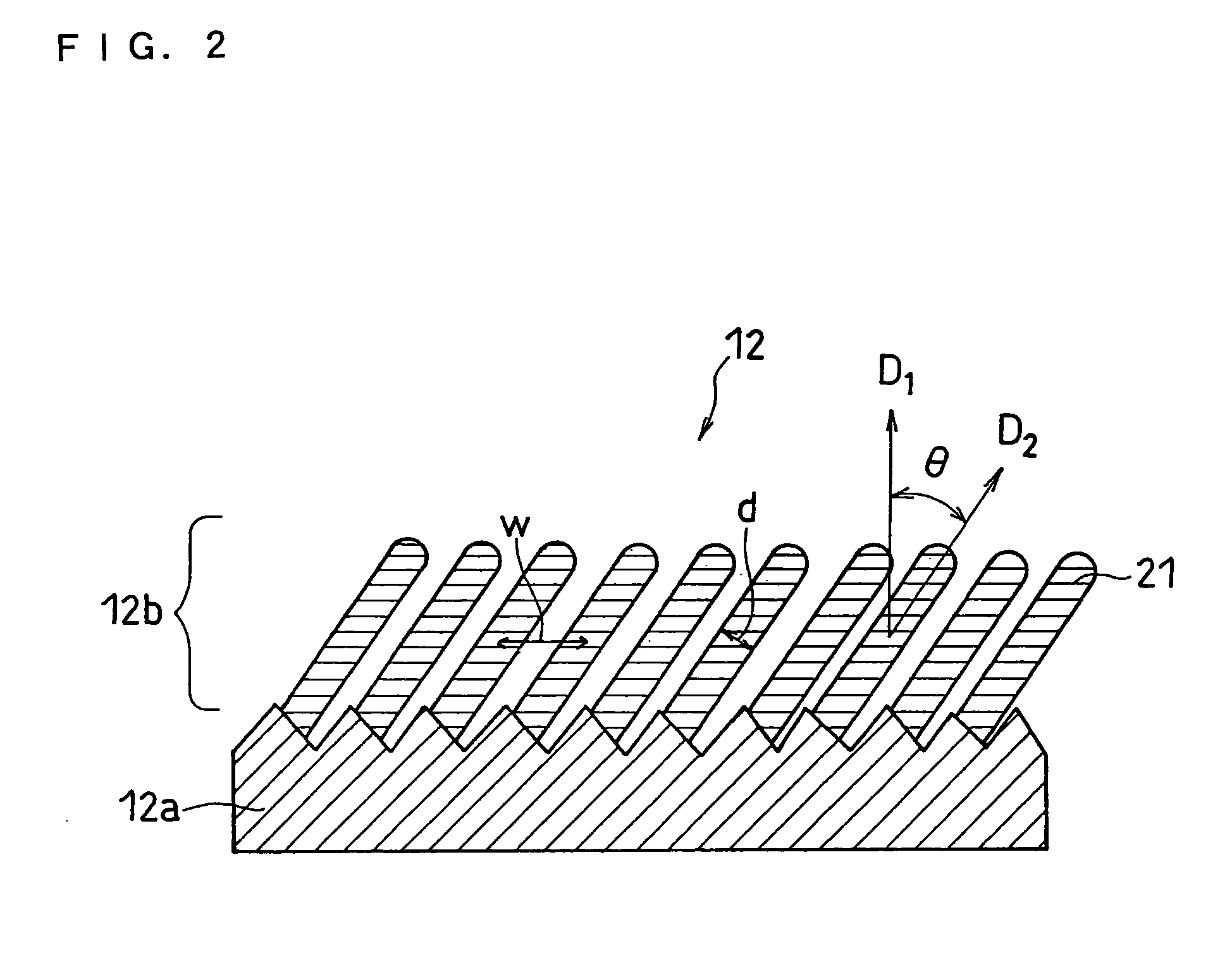
[0120] Negative electrodes 2A to 2F below were made in the same manner as Example 1, except that in the formation of a negative electrode active material, a surface roughness Rz of the electrolyte copper foil was changed, while changing an angle α formed by the fixing board 35 of the vapor-deposition apparatus in FIG. 3 and the horizontal plane, adjusting conditions for vapor-deposition, and changing an angle θ formed by the current collector and the columnar particles. Additionally, Test Batteries 2A to 2F were made in the same manner as Example 1, except that the negative electrodes 2A to 2F were used.

Negative Electrode 2A

[0121] A negative electrode was prepared in the same manner as Example 1, except that an electrolyte copper foil with the surface roughness Rz of 30 μm was used for a current collector; an angle α formed between the fixing board 35 and the horizontal plane was set to 10°; and the vapor-deposition period was set to 14 minutes.

[0122] Properties of the negative ...

example 3

[0185] Negative electrodes 3A to 3E below were made in the same manner as Example 1, except that in the formation of a negative electrode active material, a surface roughness Rz of the electrolyte copper foil was changed. Additionally, Test Batteries 3A to 3E were made in the same manner as Example 1, except that the negative electrodes 3A to 3E were used and the thickness of the positive electrode active material layer was changed.

Negative Electrode 3A

[0186] A negative electrode 3A was made in the same manner as Example 1, except that a rolled copper foil with the surface roughness Rz of 0.3 μm was used for a current collector. Test battery 3A was made in the same manner as Example 1, except that the negative electrode 3A was used, while the thickness of the positive electrode active material layer was changed to 71 μm.

[0187] Properties of the negative electrode 3A are summarized below. [0188] Composition of Active Material: SiO0.5 [0189] Angle θ Formed Between Column-like part...


PUM

PropertyMeasurementUnit
angleaaaaaaaaaa
angleaaaaaaaaaa
porosityaaaaaaaaaa

Abstract

In order to enhance charge and discharge efficiency and to improve cycle characteristics by increasing a facing area between a positive electrode active material and a negative electrode active material, in a negative electrode for lithium secondary battery having a current collector and an active material layer carried on the current collector, the active material layer includes a plurality of columnar particles. The columnar particles include an element of silicon, and are tilted toward the normal direction of the current collector. Angle θ formed between the columnar particles and the normal direction of the current collector is preferably 10°≦θ<90°.

Description

BACKGROUND OF THE INVENTION [0001] The present invention relates to a negative electrode for lithium secondary battery, the negative electrode comprising a current collector and an active material layer carried on the current collector, the active material layer comprising particles grown like columns (columnar particles), and the columnar particles including silicon as a constituent element. [0002] With the development of portable devices such as a mobile phone and a personal computer in these days, a demand for a battery as a power source for such devices is increasing. In a battery for such devices, the usage at ordinary temperatures is demanded, as well as a high energy density and excellent cycle characteristics. [0003] For such demands, a new active material with a higher capacity has been developed for a positive electrode and for a negative electrode, respectively. Among these newly developed active materials, the simple substance, an oxide, or an alloy of silicon (Si) or ti...

Claims


Application Information

Patent Timeline
Patent Type & Authority Applications(United States)
IPC IPC(8): H01M4/70H01M4/66H01M4/58H01M4/13H01M4/134H01M4/136H01M4/139H01M4/1395H01M4/1397H01M4/38H01M4/48H01M4/485
CPCH01M4/134H01M4/1395H01M4/38Y10T29/49115Y02E60/122H01M4/0426H01M4/0423H01M2004/021Y02E60/10Y02P70/50H01M4/13H01M4/36H01M10/052
Inventor KOGETSU, YASUTAKAUGAJI, MASAYATAKAHASHI, KEIICHIMINO, SHINJINAGAO, NOBUAKISHIBUTANI, SATOSHIHONDA, KAZUYOSHI
Owner PANASONIC CORP
Why Eureka
Try Eureka