Control apparatus for internal combustion engine

Active Publication Date: 2007-02-15
MITSUBISHI ELECTRIC CORP
View PDF9 Cites 13 Cited by
  • Summary
  • Abstract
  • Description
  • Claims
  • Application Information

AI Technical Summary

Benefits of technology

[0019] The present invention has been made to solve the problem described above, and an object of the present invention is therefore to provide a control apparatus for an internal combustion engine which is designed to make a changeover between a normal proportional gain and a post-fuel-cut proportional gain set larger than the normal proportional gain, to thereby ensure quick recovery of the storage amount of oxygen saturated due to the fuel cut, restore the capacity of the catalytic to absorb air-fuel ratio disturbances, and suppress torque fluctuations through prevention of overcorrection of the air-fuel ratio during normal operation.
[0020] A control apparatus for an internal combustion engine according to the present invention includes: an exhaust system of the internal combustion engine; a catalytic converter disposed in the exhaust system, for purifying an exhaust gas; upstream-side air-fuel ratio detecting means for detecting an air-fuel ratio upstream of the catalytic converter; downstream-side air-fuel ratio detecting means for detecting an air-fuel ratio in the exhaust gas downstream of the catalytic converter; air-fuel ratio adjusting means for adjusting the air-fuel ratio through adjustment of an amount of fuel supplied to the internal combustion engine; downstream-side target air-fuel ratio storing means for storing and retaining a target value for the air-fuel ratio downstream of the catalytic converter; downstream-side control means for calculating an upstream-side tar

Problems solved by technology

However, the oxygen concentration sensor provided upstream of the catalytic converter is exposed to a high-temperature exhaust gas, causing output fluctuations, so the oxygen concentration sensor provided downstream of the catalytic converter is used to correct errors.
However, if the proportional gain is set large, the amount of fuel supplied to the internal combustion engine significantly c

Method used


Image

  • Control apparatus for internal combustion engine
  • Control apparatus for internal combustion engine
  • Control apparatus for internal combustion engine

Examples


first embodiment

[0035] A control apparatus for an internal combustion engine according to a first embodiment of the present invention will be described hereinafter with reference to the drawings.

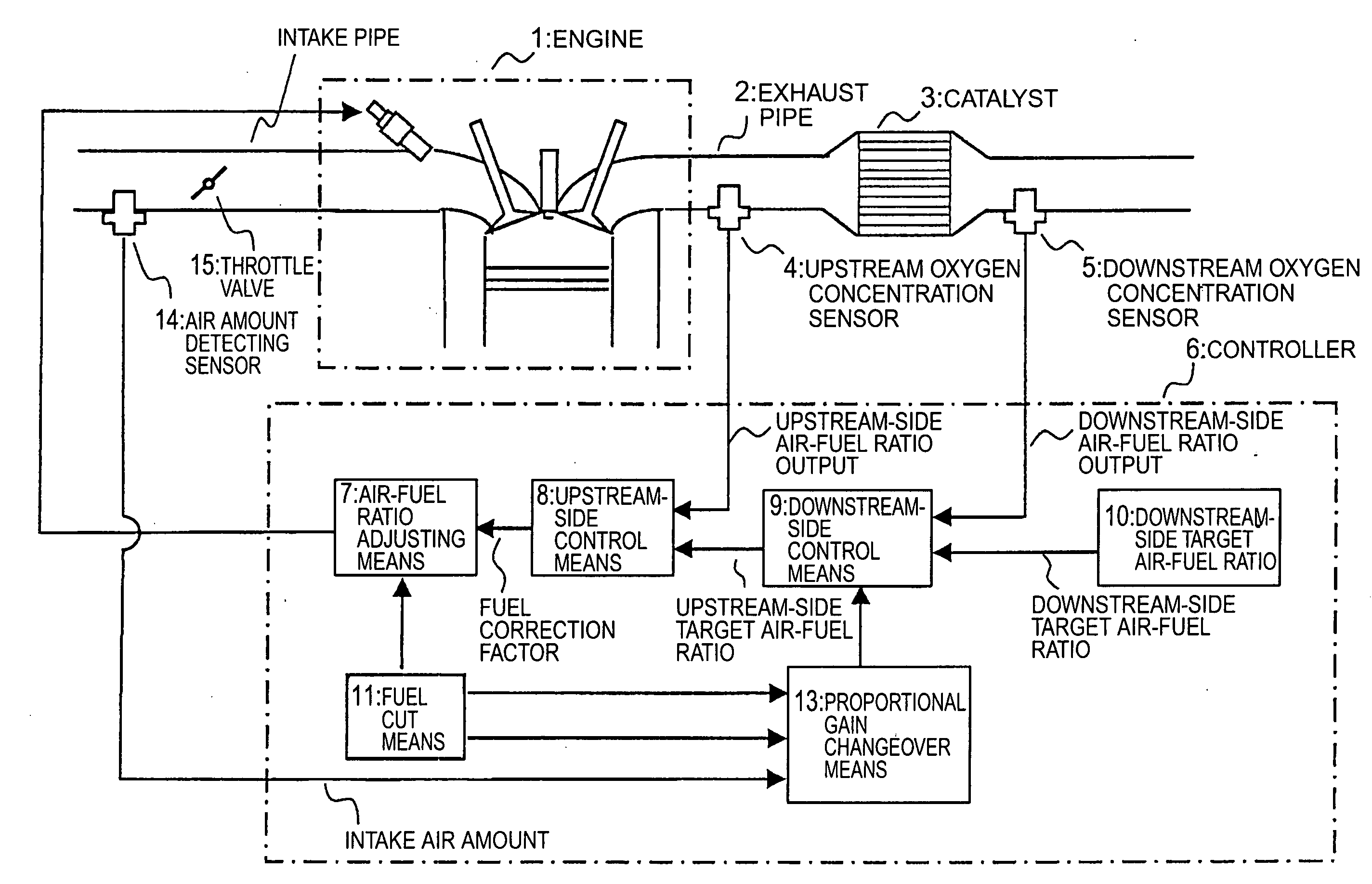
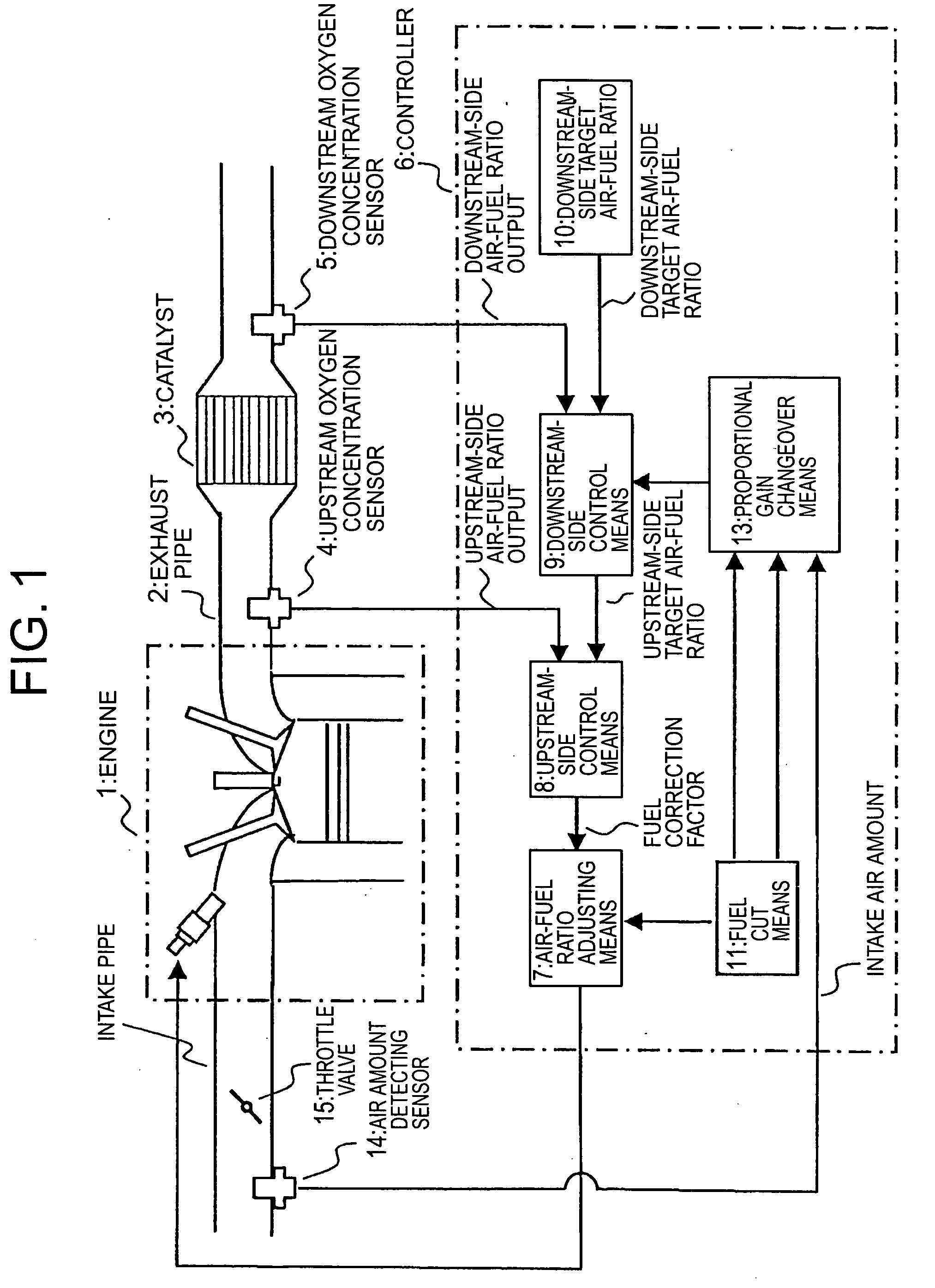
[0036]FIG. 1 is a diagram showing a configuration of the control apparatus for an internal combustion engine according to the first embodiment of the present invention.

[0037] As shown in FIG. 1, the control apparatus for an internal combustion engine controls an air-fuel ratio, that is, the ratio between air and fuel (air / fuel) supplied to an engine 1 as the internal combustion engine.

[0038] Disposed in an exhaust pipe 2 of the engine 1 is a catalytic converter 3 for simultaneously purifying poisonous components HC, CO, and NOx in the exhaust gas discharged from the engine 1.

[0039] An upstream oxygen concentration sensor 4 is an O2 sensor for detecting the concentration of oxygen in the exhaust gas upstream of the catalytic converter 3, and a downstream oxygen concentration sensor 5 is an O2 sensor for ...

second embodiment

[0165] In the first embodiment, in order to ensure coincidence between the air-fuel ratio upstream of the catalytic converter 3 and the upstream-side target air-fuel ratio, the fuel supply amount is operated in a feedback manner by transmitting the upstream-side air-fuel ratio output detected by the upstream oxygen concentration sensor 4 to the upstream-side control means 8. The control of the fuel supply amount is not limited to this method.

[0166] That is, with the control apparatus for an internal combustion engine according to the second embodiment of the present invention, quick recovery of the storage amount of saturated oxygen is required, while, for example, the proportional gain has been set to the post-fuel-cut gain, so the fuel supply amount may be operated in a feedforward manner based on the upstream-side target air-fuel ratio by the air-fuel ratio adjusting means 7 without using the upstream-side air-fuel ratio output or the upstream-side control means 8.

[0167] This m...

third embodiment

[0171]FIG. 11 is a diagram showing characteristics of the proportional gain with respect to the stoichiometric air-fuel ratio in a control apparatus for an internal combustion engine according to a third embodiment of the present invention.

[0172] Although the post-fuel-cut proportional gain Kpr_fc is set constant in the second embodiment, the control of the fuel supply amount is not limited to this method.

[0173] That is, in the control apparatus for an internal combustion engine according to the third embodiment of the present invention, the post-fuel-cut proportional gain Kpr_fc may be set larger than the normal gain Kpr_nr on the lean side with respect to the downstream-side target air-fuel ratio (in a region where the difference ΔVr between the downstream-side target air-fuel ratio and the downstream-side air-fuel ratio output in the equation (1) is positive) as shown in, for example, FIG. 11.

[0174] Owing to such control, the operation amount required for recovery of the satur...


PUM


Abstract

A control apparatus for an internal combustion engine, which makes it possible to ensure quick recovery of a storage amount of oxygen saturated due to a fuel cut, to restore the capacity of a catalytic converter to absorb air-fuel ratio disturbances, and to suppress torque fluctuations through prevention of overcorrection of the air-fuel ratio during normal operation. The control apparatus for an internal combustion engine according to the present invention is equipped with a proportional gain changeover unit. This unit makes a changeover in a proportional gain for proportional calculation in a downstream-side control unit for a predetermined period from a normal proportional gain to a post-fuel-cut proportional gain set larger than the normal proportional gain by a predetermined value, when a fuel cutoff unit starts cutting the fuel supply.

Description

BACKGROUND OF THE INVENTION [0001] 1. Field of the Invention [0002] The present invention relates to a control apparatus for an internal combustion engine. [0003] 2. Description of the Related Art [0004] In present-day automobiles, a three-way catalyticis installed in an exhaust passage of an internal combustion engine to purify the exhaust gas. As is well known, the three-way catalytic exhibits a high purification ratio for any one of HC, CO, and NOx in the neighborhood of the stoichiometric air-fuel ratio, so air-fuel ratio control is performed with oxygen concentration sensors provided upstream and downstream of the catalytic so that the atmosphere of the catalytic is maintained in the neighborhood of the stoichiometric air-fuel ratio. [0005] The air-fuel ratio upstream of a catalytic converter is controlled to a value in the neighborhood of the stoichiometric air-fuel ratio using the oxygen concentration sensor provided upstream of the catalytic converter. However, the oxygen co...

Claims


Application Information

Patent Timeline
IPC IPC(8): F01N3/00
CPCY02T10/47F01N9/00Y02T10/40
Inventor TAKUBO, HIDEKI
Owner MITSUBISHI ELECTRIC CORP
Why Eureka
Try Eureka