Apparatus for determining and/or monitoring the filling level of a product in a container

a technology for measuring and monitoring the filling level of products, applied in the direction of engine lubrication, liquid/fluent solid measurement, reradiation, etc., can solve the problem of particularly large cross section of solid individual wires, and achieve the effect of high flexibility, simple installation and high abrasion resistan

Inactive Publication Date: 2007-02-15
EHNDRESS KHAUZER GMBKH KO KG
View PDF1 Cites 9 Cited by
  • Summary
  • Abstract
  • Description
  • Claims
  • Application Information

AI Technical Summary

Benefits of technology

[0033] The object is achieved according to a first embodiment by the waveguide being a wire cable which comprises a plurality of individual wires of a predetermined diameter, the individual wires being twisted together. The embodiment of the waveguide according to the invention is distinguished by high flexibility, whereby transport and simple installation are ensured. The comparatively large diameter of the individual wires has the effect that their abrasion resistance is very high. For example, cables of the 1×19 type are superior in this respect even to plastic-coated cables. Furthermore, because of the smooth surface of the individual wires, the tensile forces in solid materials are lower than in the case of the rough stranded wires previously used. In addition, the material cross section in the case of the solid individual wires is particularly great. This is reflected in a particularly high tensile load-bearing capacity. Since only the relatively thick individual wires of the outer layer come into contact with the product in the case of the apparatus according to the invention, the number of lossy contact points between the individual wires is very small. The measuring signals consequently only experience low attenuation.
[0035] In the case of wire cables comprising, for example, three layers, the twisting of two successive layers in opposite directions produces a very high resistance to twisting in the product. The wires are consequently not twisted apart. Among the wire cables produced in the standard way, cables of the 1×19 type have incidentally the lowest attenuation for the measuring signals. One reason for this is that the surface is comparatively smooth; another reason is that the pitch in the outer layer is particularly great, which is advantageous for the current flowing exclusively in the axial direction of the only weakly attenuated fundamental mode of the wave propagation, since comparatively few contact points between the individual wires then have to be overcome. This is reflected in the low losses through the contact points.
[0039] The object is achieved according to a further embodiment by the waveguide being a flexible element absorbing the tensile forces occurring (wire cable, plastic cable, hose or the like) which is surrounded on its surface by a metal mesh. This reduces the attenuation, since on the one hand the surface is quite smooth and since on the other hand, even if the current flow between the individual wires is prevented by high contact resistances, altogether only an axial current flows as a result of the braiding in a crisscross arrangement. This is advantageous for the propagation of the low-attenuation fundamental mode on the waveguide, since the radial components of the current in the individual wires compensate for one another, while the axial components of the current are cumulative. The wire cable may be, for example, twisted stranded wires or individual wires.

Problems solved by technology

In addition, the material cross section in the case of the solid individual wires is particularly great.

Method used


Image

  • Apparatus for determining and/or monitoring the filling level of a product in a container
  • Apparatus for determining and/or monitoring the filling level of a product in a container
  • Apparatus for determining and/or monitoring the filling level of a product in a container

Examples


Embodiment Construction

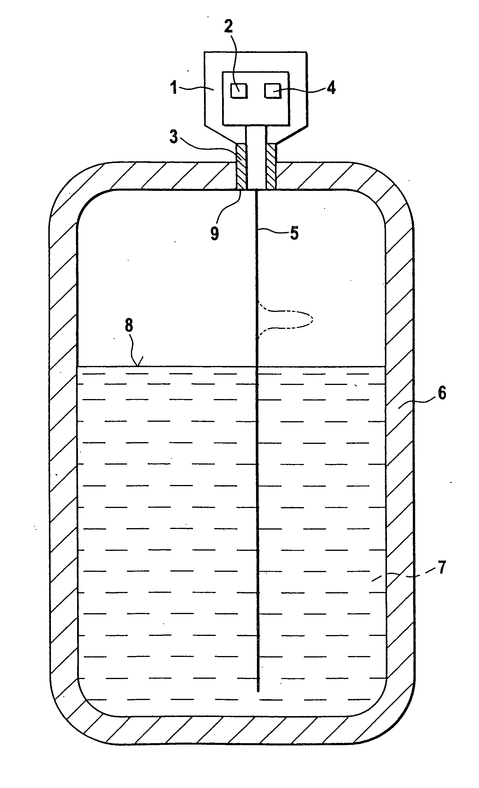
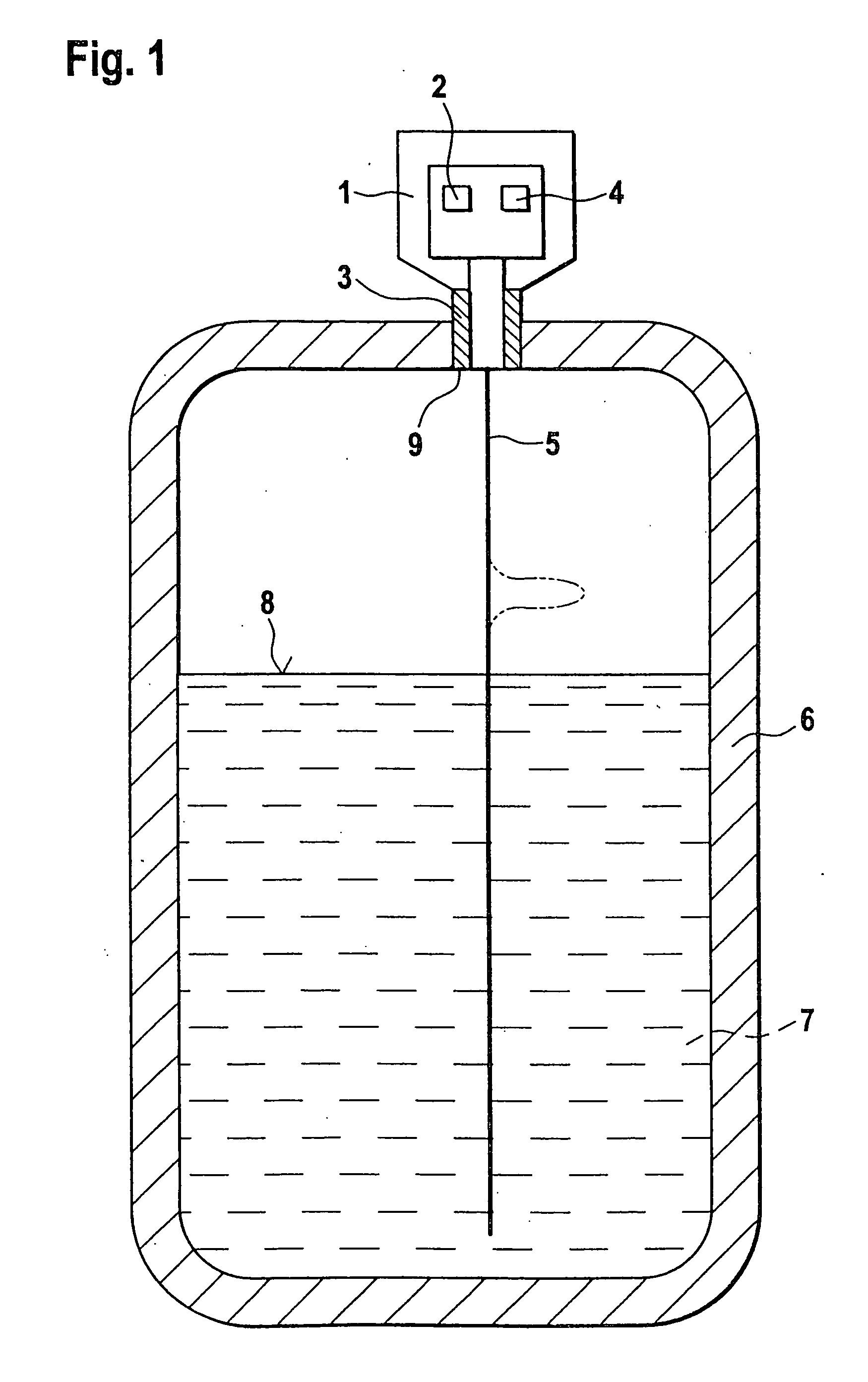
[0047]FIG. 1 shows a schematic representation of the apparatus according to the invention. The product 7 of which the filling level is to be detected is located in the container 6. Mounted in an opening 9 in the cover of the container 6 is the filling-level measuring apparatus 1. High-frequency measuring signals are guided along a waveguide 5 in the direction of the surface 8 of the product 7. Incidentally, a measuring signal is represented in a stylized form in FIG. 1 as a high-frequency pulse. The measuring signals are generated in the signal-generating unit 2 and coupled in onto the waveguide 5 via the coupling-in unit 3. The echo signals reflected at the surface 8 of the product 7 are fed to the receiving / evaluating unit 4 via the coupling-in unit 3. On the basis of the delay time and with knowledge of the height of the container 6, the evaluating unit calculates the filling level of the product 7 in the container 6.

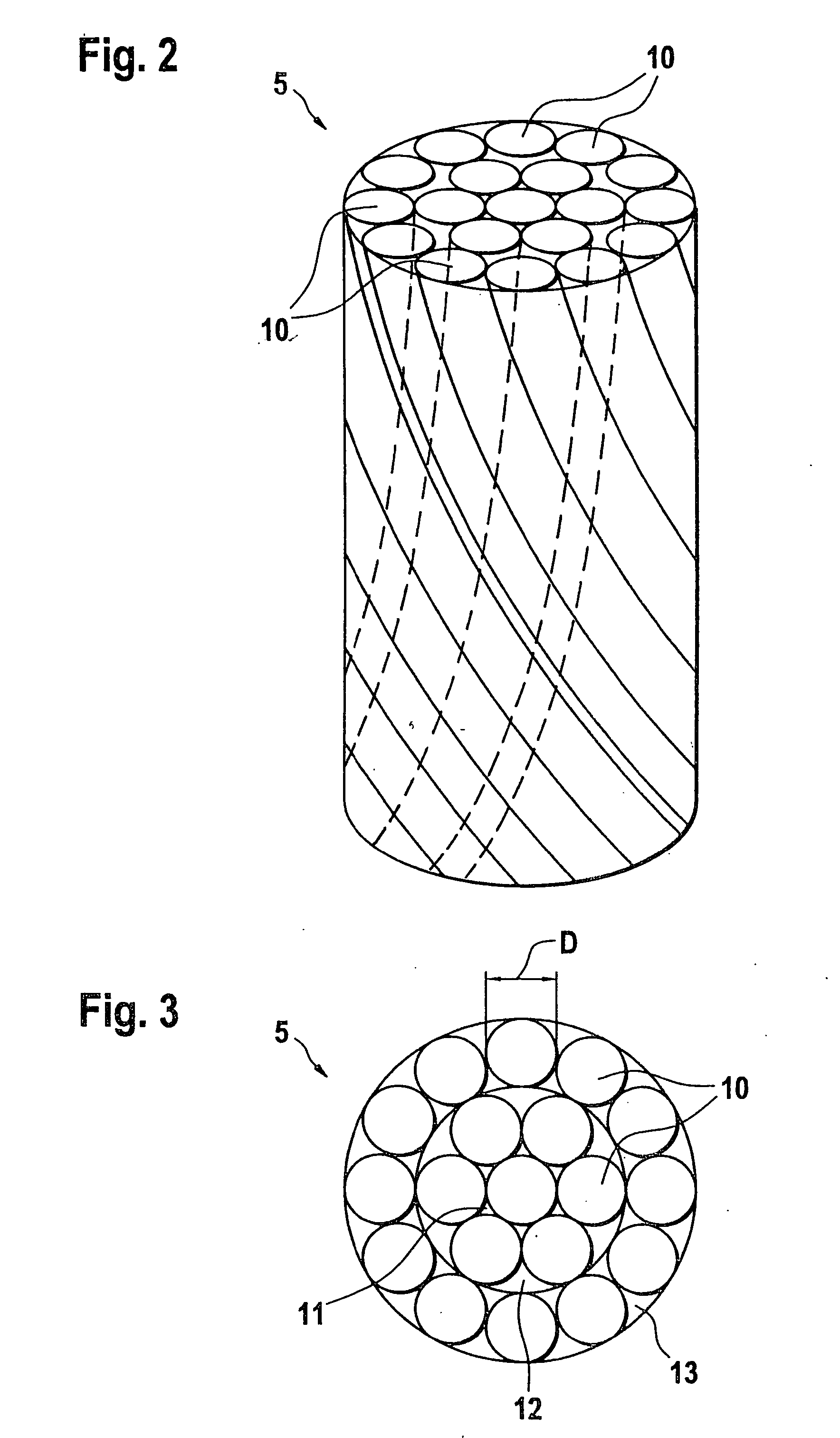
[0048]FIG. 2 shows a side view of a waveguide 5, and FIG. 3 sh...


PUM


Abstract

The invention relates to a measuring device which determines the filling level by means of high-frequency measuring signals which are guided along a waveguide. The invention is based on the object of optimizing the waveguide. According to a preferred embodiment of the apparatus according to the invention, the waveguide is a wire cable which comprises a plurality of individual wires of a predetermined diameter which are twisted together.

Description

[0001] This is a continuation of U.S. patent application Ser. No. 09 / 899,502 which was filed on Jul. 6, 2001 which has been allowed.FIELD OF THE INVENTION [0002] The present invention relates to an apparatus for determining and / or monitoring the filling level of a product or the position of the interface between two media or phases in a container, with a signal-generating unit, which generates high-frequency measuring signals, a coupling-in unit and a waveguide, the measuring signals being coupled in onto the waveguide via the coupling-in unit and conducted in the direction of the product via the waveguide, and with a receiving / evaluating unit, which determines the filling level of the product or the position of the interface in the container directly or indirectly via the delay time of the measuring signals reflected at the surface or interface of the product. BACKGROUND OF THE INVENTION [0003] In the case of delay-time methods of determining the filling level using guided electrom...

Claims


Application Information

Patent Timeline
Patent Type & Authority Applications(United States)
IPC IPC(8): G01F23/284
CPCG01F23/284
Inventor REIMELT, RALFSCHROTH, HERBERTWENDLER, ARMIN
Owner EHNDRESS KHAUZER GMBKH KO KG
Why Eureka
Try Eureka