Microfluidic separating and transporting device

a technology of microfluidics and transporting devices, which is applied in the direction of valve arrangements, laboratory glassware, thin material processing, etc., can solve the problems of consuming more energy, affecting the application of microfluidic systems, and requiring high-precision signal control, so as to increase the test types of microfluidics, promote the microfluidic mixing efficiency of biological chips, and simplify the transport process of microfluids

Inactive Publication Date: 2007-02-15
NATIONAL TSING HUA UNIVERSITY
View PDF9 Cites 18 Cited by
  • Summary
  • Abstract
  • Description
  • Claims
  • Application Information

AI Technical Summary

Benefits of technology

[0010] Another objective of the present invention is to provide a microfluidic separating and transporting device, which can promote the microfluidic mixing efficiency of biological chips, increase test types of microfluids, simplify the transporting process of microfluids and reduce the fabrication cost of biological chips.
[0011] Further another objective of the present invention is to provide a microfluidic separating and transporting device, which can use less elements and parameters to achieve easy operation, high power efficiency, high biological compatibility, automation and simplified fabrication process, and may be contributive to the future integration of microfluidic transporting systems.

Problems solved by technology

Thus, the application of microfluidic systems may be limited.
For example, when a biomedical test is undertaken, externally applied thermal energy may raise the temperature of tested solutions, and an externally applied electric field may polarize the substances distributed inside microfluids; thus, the characteristics of solutions and biological molecules may be changed, and the correction of test results may be affected.
However, the conventional technology mentioned above needs high precision signal control and consumes more energy.
Thus, the design of the elements thereof and the development of the fabrication process thereof are relatively complicated, and the cost thereof is also raised.
Further, there are too many parameters needing considering and controlling, such as the delay time between signal receiving and droplet generation, the size and type of the droplet, the distance between the outlet of the droplet injector and the surface of the rotary disc, the time the droplet needs to reach the inlet of the microchannel, the rotation speed of the rotary disc, etc.
Too many control parameters cause difficulties in operating the system and maintaining the reliability of the system.

Method used


Image

  • Microfluidic separating and transporting device
  • Microfluidic separating and transporting device
  • Microfluidic separating and transporting device

Examples


Embodiment Construction

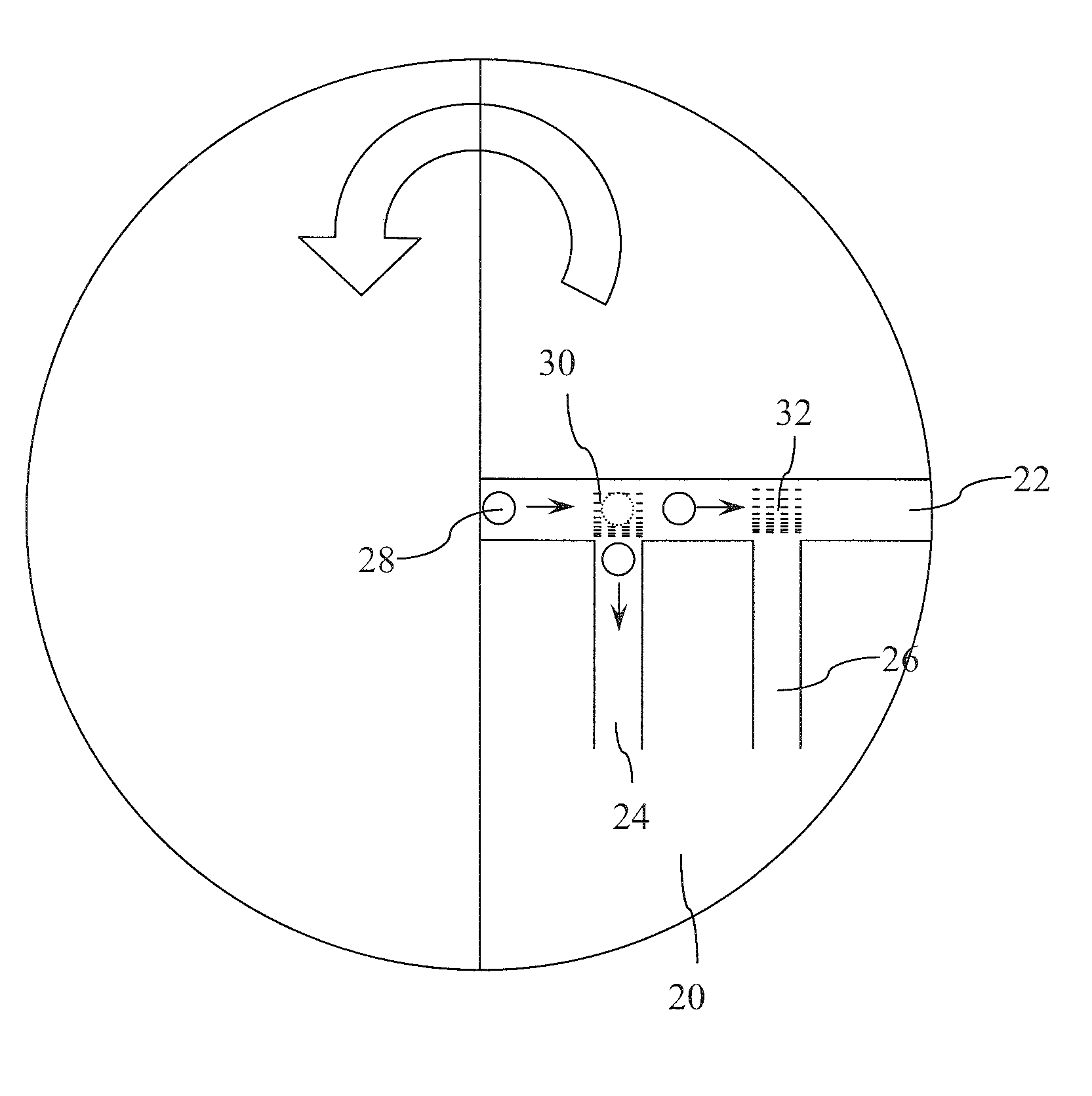
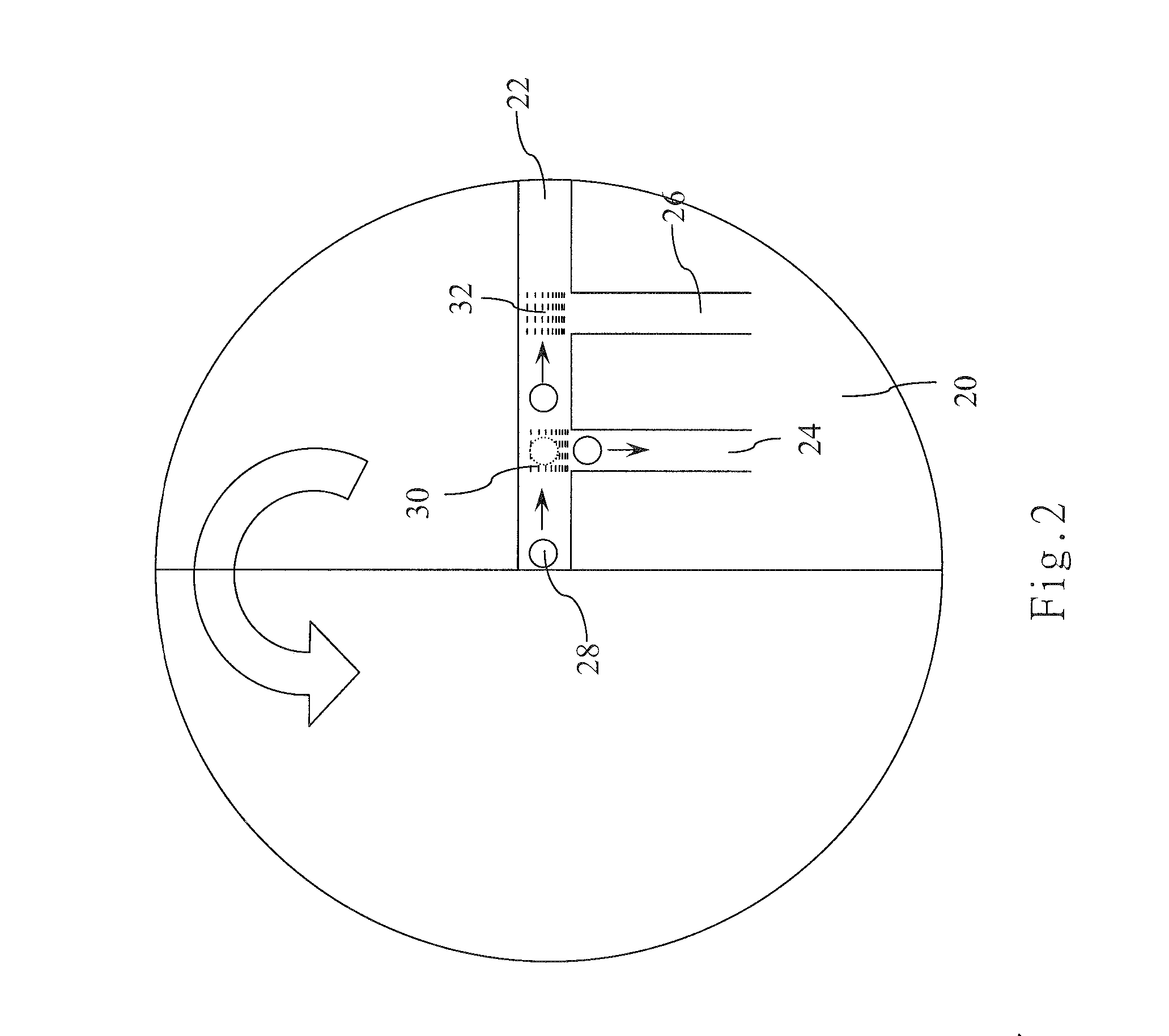
[0018] The present invention utilizes a physical or chemical method to fabricate density-variation surface energy gradient microstructures, i.e. rare-to-dense microstrip patterns, which create different surface tension gradients between microfluids and the inner walls of the microchannels along the flowing direction of the microfluids to drive the microfluids to flow automatically. The microfluids flow to the bifurcation regions between the primary microchannel and the secondary microchannels spontaneously via the driving force of surface tension gradient. The bifurcation regions connect with the secondary microchannels having density-variation micro / nano structures, which enable the secondary microchannels to have different hydrophobias. Thus, when the microfluids flow to the bifurcation regions, they will respectively enter into the microchannels having their own hydrophobias. Thereby, the microfluids can be precisely and automatically separated and guided to the assigned secondar...


PUM


Abstract

The present invention discloses a microfluidic separating and transporting device, which utilizes free-energy gradient surfaces having micro / nano physical and chemical properties to drive and separate microfluids automatically. The device of the present invention comprises a platform having microchannels. The surfaces of the microchannels have surface energy gradient-inducing rare-to-dense microstructures. The rare-to-dense microstructures are formed in two regions; one is formed in the primary microchannel and used to transport microfluids, and the other is formed in the microfluid bifurcation region. When different microfluids flow through the microfluid bifurcation region, the microfluids will separate automatically to their own secondary microchannels according to the surface energy gradient. Thereby, droplets of different microfluids can be separated apart or split into diffluences.

Description

BACKGROUND OF THE INVENTION [0001] 1. Field of the Invention [0002] The present relates to a microfluidic separating and transporting device, particularly to a microfluidic separating and transporting device, wherein the surface energy gradient of microfluids, which is induced by a micro / nano structure fabricated with a microelectromechanical technology, is used to separate microfluidic droplets. [0003] 2. Description of the Related Art [0004] When a biochemical analysis is undertaken in a microfluidic chip, a series of different droplets is transported, separated and mixed in microchannels. The key technology of microfluidic systems is the control technology of microfluids. As the dimension of microfluidic systems has been reduced to micrometer scale, surface tension outweighs gravity and becomes the major driving force of microfluidic systems. Surface tension is in a linear relationship with length, i.e. F=γ×λ. Therefore, the smaller the system, the greater the influence of surfac...

Claims


Application Information

Patent Timeline
Patent Type & Authority Applications(United States)
IPC IPC(8): F15C1/06
CPCB01L3/50273F16K2099/0084B01L3/502792B01L2300/0803B01L2300/0864B01L2300/165B01L2400/0406B01L2400/0409B01L2400/0427B01L2400/0448B01L2400/0622B01L2400/0688B01L2400/088F16K99/0001F16K99/0017F16K99/0021B01L3/502761Y10T137/2224
Inventor YANG, JING-TANGCHEN, CHIEN-YANGYANG, TZUNG-HANCHEN, TSUNG-YU
Owner NATIONAL TSING HUA UNIVERSITY
Why Eureka
Try Eureka