Heat-dissipation structure and method thereof

a heat-dissipation and structure technology, applied in the direction of lighting and heating apparatus, cooling/ventilation/heating modification, semiconductor devices, etc., can solve the problems of increasing the manufacturing cost of the heat-dissipation device, affecting the heat dissipation effect, and correspondingly increasing the waste heat generated by the ic. , to achieve the effect of rapid heat dissipation

Inactive Publication Date: 2007-02-15
COOLER MASTER CO LTD
View PDF9 Cites 25 Cited by
  • Summary
  • Abstract
  • Description
  • Claims
  • Application Information

AI Technical Summary

Benefits of technology

[0009] Accordingly, an objective of the present invention is to provide

Problems solved by technology

However, as the processing speed and function of the ICs are significantly increased, the waste heat generated by the IC also correspondingly increases significantly, and if the waste heat cannot be effectively dissipated, the electronic device failure occurs.
However, the volume of the heat-dissipation device 100 must be increased to accommodate more heat-dissipation fins 120, which increases the manufacturing cost of the heat-dissipation device 100, and the weight of th

Method used


Image

  • Heat-dissipation structure and method thereof
  • Heat-dissipation structure and method thereof
  • Heat-dissipation structure and method thereof

Examples


Embodiment Construction

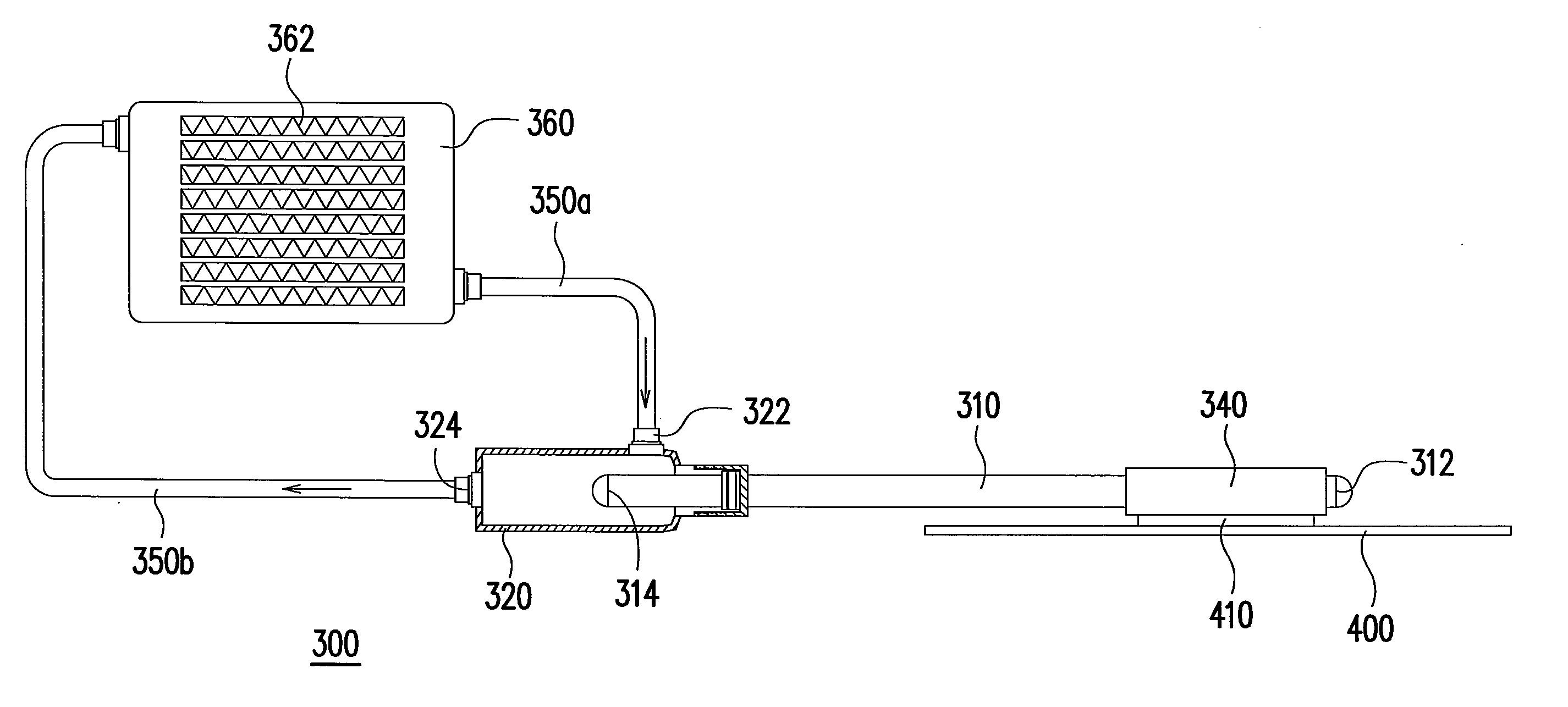
[0038]FIG. 3A is a schematic exploded view of components of a heat-dissipation structure according to an embodiment of the present invention. Referring to FIG. 3A, the heat-dissipation method of the present embodiment mainly comprises conducting heat to a tube jacket 320 via a heat pipe 310, and dissipating the heat by circulation flow of fluid in the tube jacket 320. Moreover, the heat pipe 310 is connected to the tube jacket 320 via a joint 330, as shown in FIG. 3B. Since the heat pipe 310 is an important feature of the present invention, the structure of the heat pipe 310 is illustrated in detail in accompany with the figure below.

[0039]FIG. 4A is a schematic sectional view of the heat pipe of FIG. 3A. Referring to FIG. 4A, the heat pipe 310 comprises a heated end 312 (first end) and a cooling end 314 (second end). When a temperature difference exists between the heated end 312 and the cooling end 314, the heat pipe 310 rapidly conducts the heat of the heated end 312 to the cool...


PUM


Abstract

A heat-dissipation structure mainly including a heat-absorbing head, a heat pipe, and a tube jacket is provided. The heat pipe includes a heated end and a cooling end, wherein the heated end of the heat pipe is connected to the heat-absorbing head, and a flange is projected form the surface of the heat pipe adjacent to the cooling end. A joint is disposed on the cooling end of the heat pipe, and is connected to the tube jacket through the opening, such that the cooling end is sealed inside the tube jacket, and the flange of the heat pipe is tightly fastened between the joint and the opening. The heat-dissipation structure is used to rapidly conduct the waste heat generated by a processing chip to the tube jacket via the heat pipe.

Description

CROSS-REFERENCE TO RELATED APPLICATION [0001] This application claims the priority benefit of Taiwan application serial no. 94127117, filed on Aug. 10, 2005. All disclosure of the Taiwan application is incorporated herein by reference. BACKGROUND OF THE INVENTION [0002] 1. Field of the Invention [0003] The present invention relates to a heat-dissipation structure, and more particularly to a heat-dissipation structure applicable to an electronic device. [0004] 2. Description of Related Art [0005] With the progress of semiconductor technology, integrated circuits (ICs) have been largely used in chips of an electronic device such as a personal computer, a PC notebook, and a network server. However, as the processing speed and function of the ICs are significantly increased, the waste heat generated by the IC also correspondingly increases significantly, and if the waste heat cannot be effectively dissipated, the electronic device failure occurs. Therefore, various heat-dissipation meth...

Claims


Application Information

Patent Timeline
IPC IPC(8): H05K7/20
CPCF28D15/02F28D15/0275H01L23/427H01L23/473H01L2924/0002H01L2924/00
Inventor KUO, MING-CHIEN
Owner COOLER MASTER CO LTD
Why Eureka
Try Eureka