
Charging system for charging accumulator means in an electronic device, and a charging apparatus and an electronic device for the system

a charging system and charging accumulator technology, applied in the direction of electrical equipment, electric vehicles, charging data, etc., can solve the problems of time-consuming and therefore costly, inconvenient installation, and inability to integrate two separate connectors, and achieve the effect of more flexibility

Inactive Publication Date: 2007-02-15
WEBJORN MATS
View PDF4 Cites 26 Cited by
  • Summary
  • Abstract
  • Description
  • Claims
  • Application Information

AI Technical Summary

Benefits of technology

[0006] It is an object of the present invention to provide more flexibility for connecting an electronic device comprising electrical accumulators to chargers.
[0009] Thereby, upon physical attachment of the charging apparatus to the electronic device, certain properties of the configuration can be established, in order to proceed with accumulator charging, or possibly to suspend charging if certain un-desired qualities are present in the configuration. Properties established can include maximum charging power or current. Further, the communication protocol can be used to establish whether the electronic device is being connected to a charging apparatus or an external electronic unit. Upon establishment, a connection configuration can be set for the delivery of power or exchange of data depending on the combination at hand, whether it is a charger-device combination, or something else. In other words, when the charging apparatus and the electronic device are connected, the communication protocol can be used to establish this, and based on this establishment, the electronic device can be configured for the accumulator means to receive charging power from the charger in a manner as efficient as possible. As a result of this, the charging apparatus or some external electronic unit can be connected to the electronic device using the same connector in the latter. In general, it will provide a flexible system with an electronic device to be connected to a charger as well as an external electronic unit. This embodiment will also, by allowing one connector on the electronic device to be used for charging and other applications, simplify the design of the electronic device, reduce manufacturing time and material needed for it, and therefore reduce production costs of the device.
[0011] Preferably, at least one application data set according to the communication protocol is stored in at least one electronic memory arranged in the electronic device, at least one of the application data sets including data requested according to the communication protocol for charging the accumulator means using the charging apparatus. Thereby, the electronic device can, by suitable entries in the electronic memory, be easily adapted for being connectable to a selected charger type or types. For example, by adding an application data set, the device can be adapted to be connected to a charger with specifications differing from other chargers, to which the device is adapted to be connected to. The application data set requested for charging the accumulator means can be arranged in any way in the electronic memory of the device, e.g. as a coherent entry. It could also be arranged in at least two data subsets distributed to different registers or similar of the memory or memories, whereby subscripts or pointers are used to link the subsets.

Problems solved by technology

For example, the user might not have the charger supplied to him together with the device handy, and he or she might be contemplating attaching a charger of another make or model to the device, without knowing if the charger specifications correspond to the requirements of the device to be charged.
In mass production, the inclusion of two separate connectors requires additional parts and materials, is time consuming and therefore costly.
For example, if the external electronic unit is a PC, power can be delivered to the electronic device for functions in the latter, but there could be requirements due to limitations in power delivery capabilities of the external electronic unit.

Method used


Image

  • Charging system for charging accumulator means in an electronic device, and a charging apparatus and an electronic device for the system
  • Charging system for charging accumulator means in an electronic device, and a charging apparatus and an electronic device for the system

Examples


Embodiment Construction

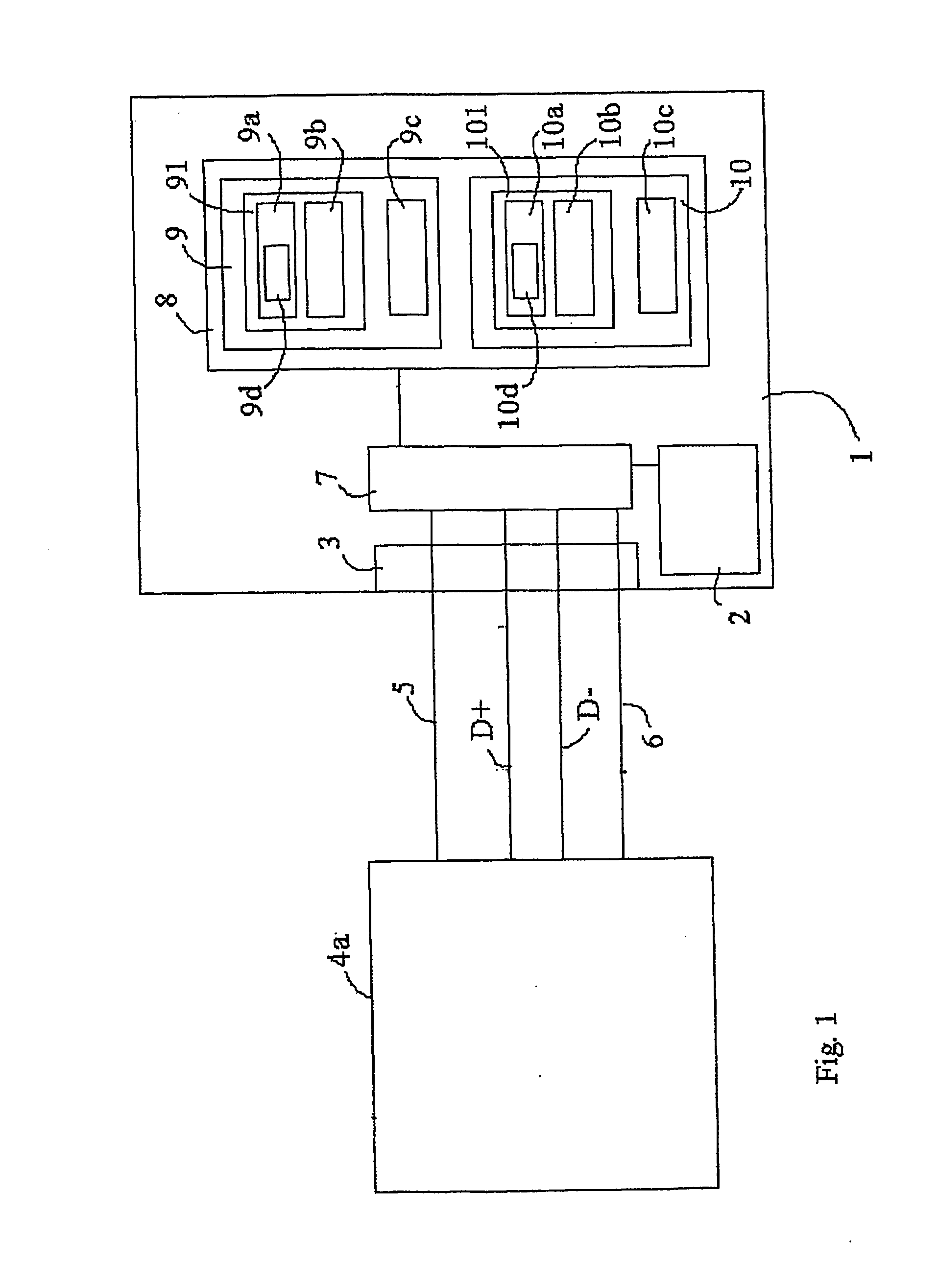
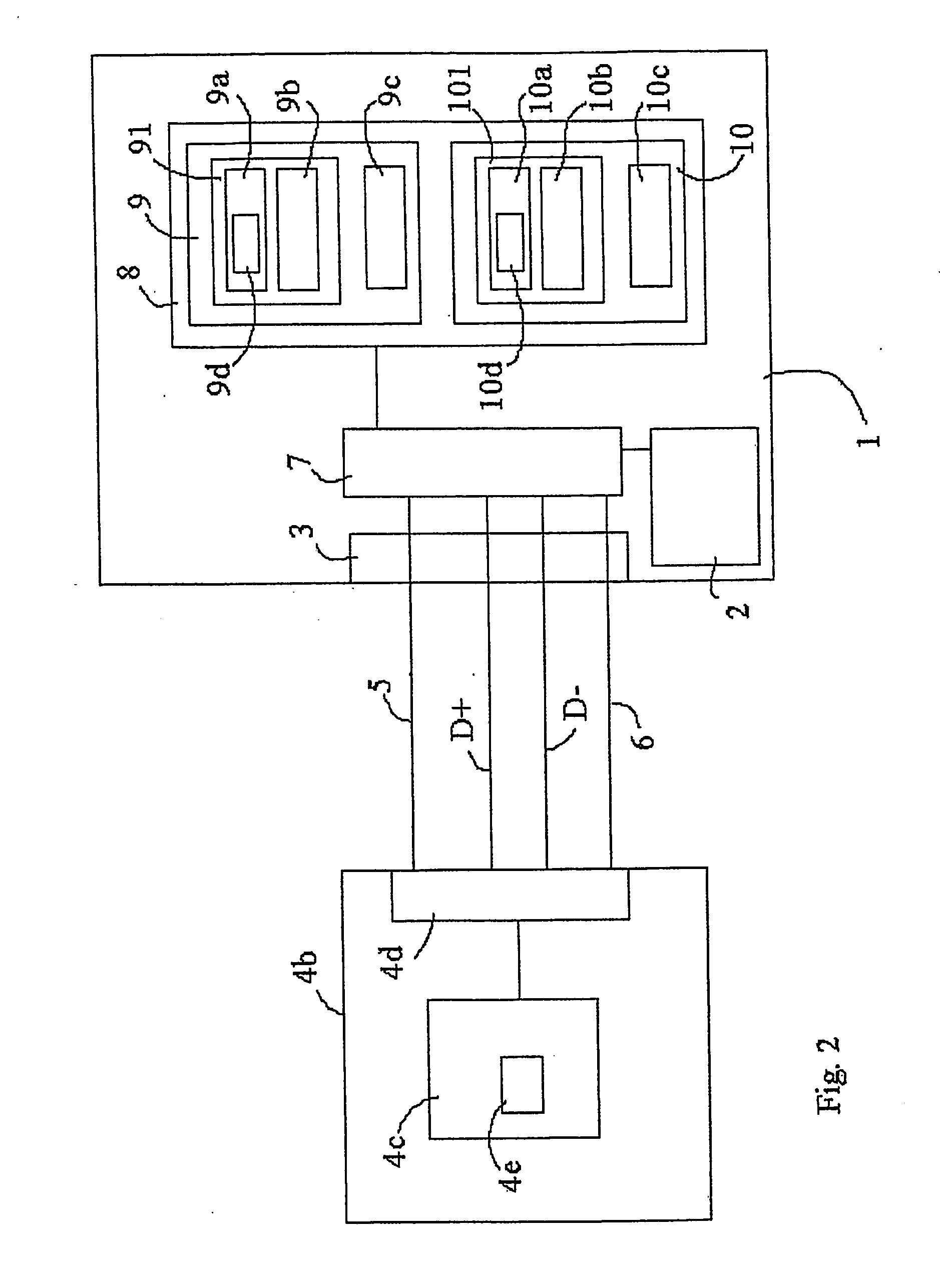
[0016]FIG. 1 is a block diagram in which an electronic device 1 is schematically depicted. The electronic device 1 comprises accumulator means in the form of one or more rechargeable batteries or accumulators. The electronic device 1 could be adapted to perform any of a number of functions associated with computer utilisation, telecommunication or other types of information technology, whereby power from the accumulator means can be used for enabling performance of such functions. For example, it could be a portable measuring device, a wireless human input device such as a wireless computer keyboard or a wireless mouse, or a mobile terminal.

[0017] The electronic device 1 comprises a connector 3 for connecting an external electronic unit 4a, e.g. via a flexible cord. For example, the external electronic unit 4a could be a personal computer (PC). Using computational and storage capabilities, described closer below, in the electronic device 1 and in the external electronic unit 4a, th...


PUM


Abstract

A charging system for charging accumulator means (2) in an electronic device (1) is provided, the electronic device (1) being adapted to be connected to a charging apparatus (4b) for charging the accumulator means (2). The charging apparatus (4b) is adapted to send, and the electronic device (1) is adapted to receive, and / or the electronic device (1) is adapted to send, and the charging apparatus (4b) is adapted to receive at least one signal according to a communication protocol for configuring the connection between the electronic device (1) and the charging apparatus (4b). Further, the electronic device (1) is adapted to be connected to an external electronic unit (4a), whereby the external electronic unit (4a) is adapted to send, and the electronic device (1) is adapted to receive, and / or the electronic device (1) is adapted to send, and the external electronic unit (4a) is adapted to receive at least one signal according to the communication protocol.

Description

TECHNICAL FIELD [0001] The present invention refers to a charging system, and also to an electronic device, and a charging apparatus for the charging system. TECHNICAL BACKGROUND [0002] Electronic devices having rechargeable accumulators, whether they are portable measuring devices, wireless computer keyboards, wireless mice, mobile terminals, simply electrical accumulators, or any other type of devices, have means to attach and connect a charger for the accumulators. Thereby, the charger required is usually of a certain type or model, often supplied to the user together with the electronic device. [0003] In many cases, there is a need for more flexibility regarding the choice of charger for the device. For example, the user might not have the charger supplied to him together with the device handy, and he or she might be contemplating attaching a charger of another make or model to the device, without knowing if the charger specifications correspond to the requirements of the device...

Claims


Application Information

Patent Timeline
Patent Type & Authority Applications(United States)
IPC IPC(8): H02J7/00H02J
CPCH02J7/0052H02J7/00H02J7/00036
Inventor WEBJORN, MATS
Owner WEBJORN MATS
Learn More