Brightness enhancement film with improved view angle

a technology of brightness enhancement and view angle, applied in the direction of planar/plate-like light guides, lighting and heating apparatuses, instruments, etc., can solve the problems of side-lobes and unsatisfactory security, and achieve the effect of small reduction of peak brightness and increased useful illumination

Inactive Publication Date: 2007-02-15
SABIC INNOVATIVE PLASTICS IP BV
View PDF39 Cites 97 Cited by
  • Summary
  • Abstract
  • Description
  • Claims
  • Application Information

AI Technical Summary

Problems solved by technology

These side-lobes can result in a waste of energy because they are outside the desired viewing angle specifications of many liquid crystal display (LCD) devices.
The side-lobes are also undesirable in security applications since they allow light to reach unintended viewers.

Method used


Image

  • Brightness enhancement film with improved view angle
  • Brightness enhancement film with improved view angle
  • Brightness enhancement film with improved view angle

Examples


first embodiment

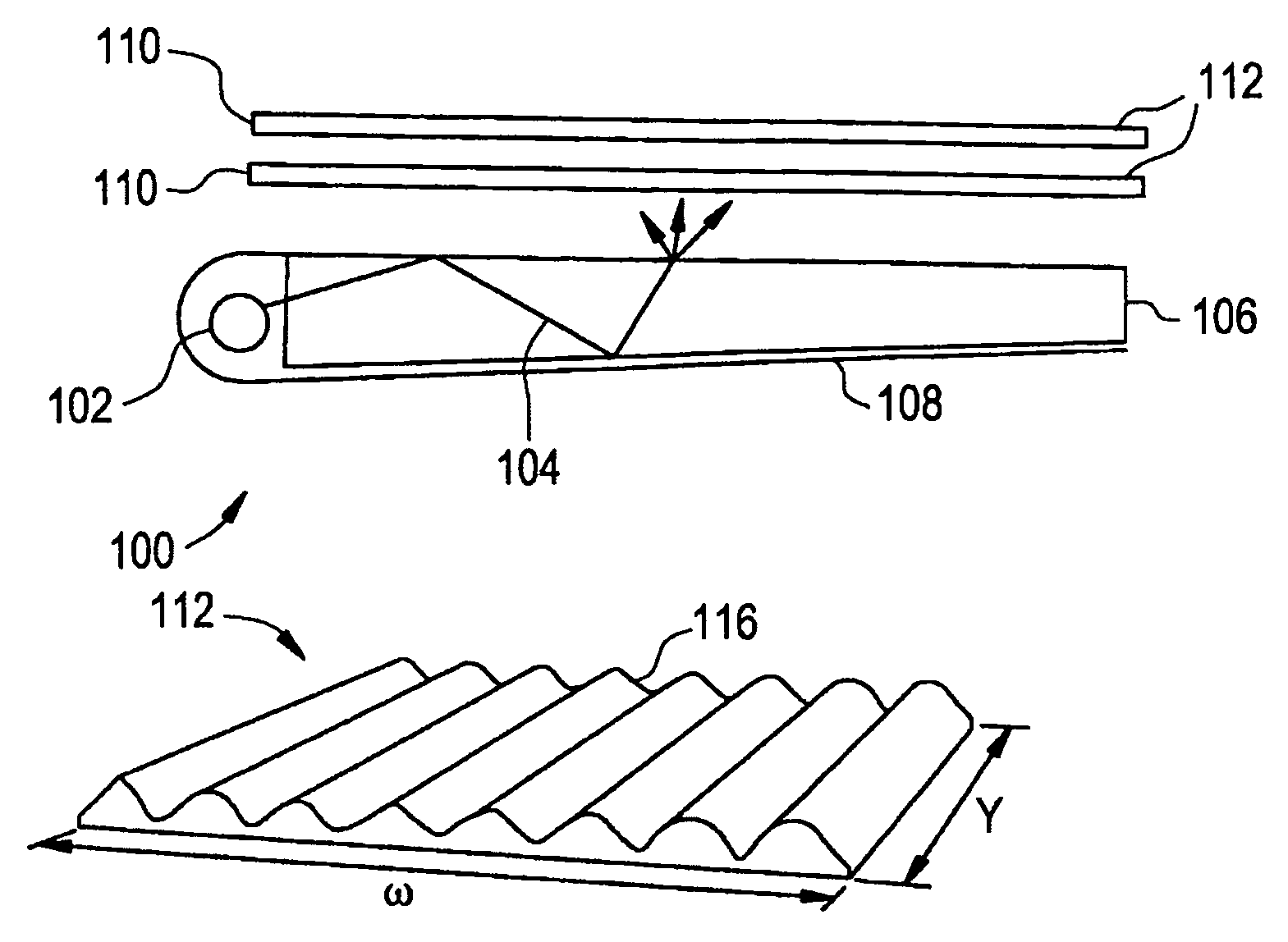
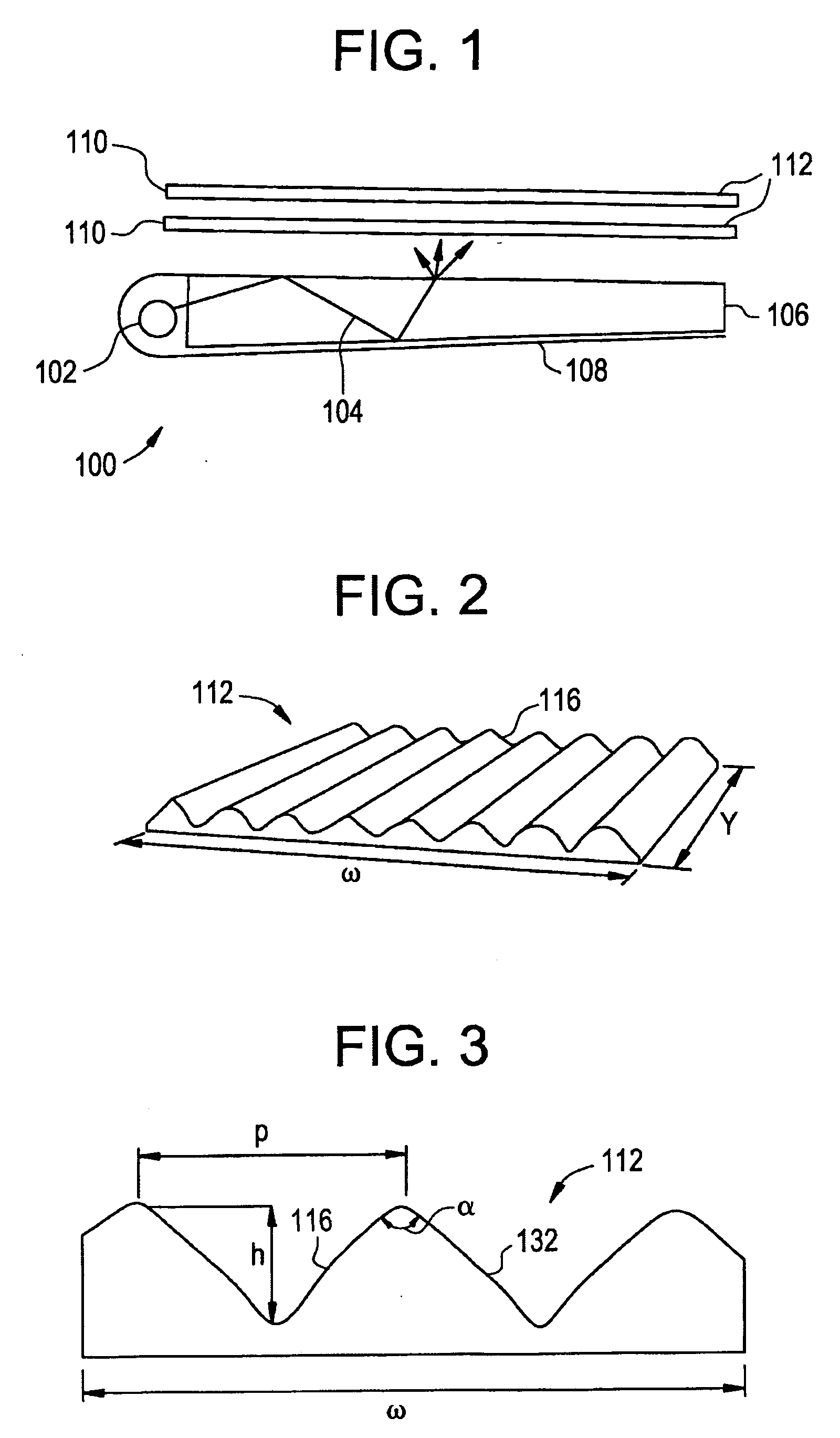
[0022] The optical substrates 110 may be positioned, one above the other, in a crossed configuration wherein the prismatic structures 116 are positioned at an angle with respect to one another (e.g., 90 degrees) as seen in FIG. 7. The prisms 116 have a prescribed peak angle, a, a height, h, a length, 1, and a pitch, p and one or both of the prismatic surfaces 112 may be randomized in their peak angle, a, height, h, length, 1, and pitch, p. Yet further, one or both sides of the substrates 110 may have the prisms 116. In FIGS. 2, 3 and 4, in the invention, the sidewall or facets 132 of the prisms 116 which comprise the surface 112 are curved. The curvature can be described as a segment of a parabola, or more generally as a polynomial surface given by the sag equation: z=cr21+1-(1+k)⁢c2⁢r2+dr2+er4+fr6+Higher⁢ ⁢order⁢ ⁢terms⁢ ⁢in⁢ ⁢r(1)

where z is the perpendicular deviation (or “sag”) in microns of the sidewall or facet 132 of the prisms 116 from a straight reference line 128, origina...

second embodiment

[0025] In a second embodiment, a relatively high index of refraction for the optical substrate 110 in combination with a modified prism geometry yields an enhanced brightness. In particular, FIG. 8 displays a map of the central luminance in per cent of crossed optical substrates as a function of the prism peak angle and the refractive index of the substrate, wherein a refractive index of 1.6 and a peak angle of 90 degrees is taken to be 100 per cent. By increasing the peak angle to 100 degrees and increasing the refractive index of the optical substrate generally to greater than about 1.65 and in particular to between approximately 1.7 and 1.8, the luminance is at least 102 per cent.

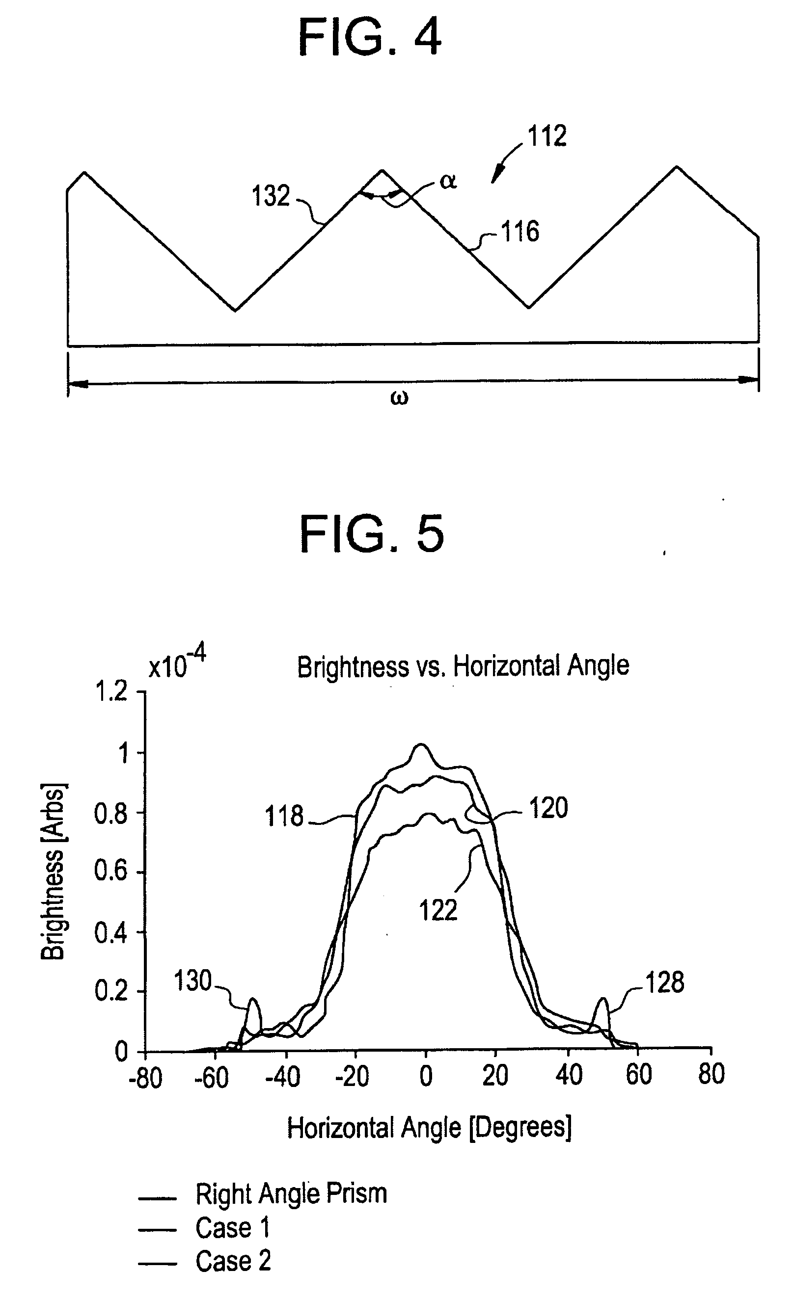
[0026]FIG. 9 shows a graphical depiction of the far field horizontal luminance of crossed optical substrates as a function of horizontal viewing angle. In FIG. 9, a prior art luminance profile, based upon a refractive index of 1.65 and a peak prism angle of 90 degrees is shown at 150. As can be seen in F...


PUM


Abstract

A structural shape on the surface of an optical substrate is such that the brightness of diffuse light departing from the surface of the optical substrate at certain off axis angles is reduced, at the expense of a small reduction in peak brightness measured near the viewing axis. The net result is an overall increase in useful illumination. A cross section of a prism as the structural shape has a curved sidewall or facet. A material with a relatively high index of refraction combined with a prismatic structure having a modified prism geometry improves brightness.

Description

CROSS-REFERENCE TO RELATED PATENT APPLICATIONS [0001] This application is a continuation of U. S. application Ser. No. 10 / 065,981, filed on Dec. 6, 2002.BACKGROUND OF THE INVENTION [0002] This invention relates to brightness enhancement films and, more specifically to such films having curved facet prism structures and increased prism peak angles and refractive indices. [0003] In backlight computer displays or other systems, optical films are commonly used to direct light. For example, in backlight displays, brightness enhancement films use prismatic structures to direct light along the viewing axis (i.e., an axis normal to the display, or “on axis”). This enhances the brightness of the light viewed by the user of the display and allows the system to use less power to create a desired level of on-axis illumination. Films for turning light can also be used in a wide range of other optical designs, such as for projection displays, traffic signals, and illuminated signs. [0004] Backlig...

Claims


Application Information

Patent Timeline
Patent Type & Authority Applications(United States)
IPC IPC(8): F21V7/04F21V8/00G02B5/02G02B6/00
CPCG02B6/0001G02B6/0031G02B6/0071G02B6/0046G02B6/005G02B6/0038G02F1/133606G02F1/133611
Inventor OLCZAK, EUGENE
Owner SABIC INNOVATIVE PLASTICS IP BV
Why Eureka
Try Eureka