
Wavelength-division-multiplexed light source and wavelength-division-multiplexed passive optical network using the same

a technology of wavelength-division multiplexing and light source, applied in multiplex communication, instruments, optical elements, etc., can solve the problems of requiring a high cost, and reducing the efficiency of signal quality, so as to achieve efficient signal quality.

Inactive Publication Date: 2007-02-15
SAMSUNG ELECTRONICS CO LTD
View PDF9 Cites 41 Cited by
  • Summary
  • Abstract
  • Description
  • Claims
  • Application Information

AI Technical Summary

Benefits of technology

[0009] Accordingly, the present invention has been made to solve the above-mentioned problems occurring in the prior art and provides additional advantages, by providing a wavelength-division-multiplexed light source capable of efficiently maintaining the signal quality by reflecting loss characteristics of transmission optical signals therein, and a wavelength-division-multiplexed passive optical network using the new wavelength-division-multiplexed light source.

Problems solved by technology

When the circulator is used, there is an advantage of reducing transmission loss of optical signals, but there is a disadvantage of requiring a high cost.
Also, when the 3 dB coupler is used, there is an advantage of having a low cost, but there is a disadvantage of causing a 3 dB coupling loss in an upstream-band light and an upstream optical signal, respectively.
However, the conventional wavelength-division-multiplexed passive optical network uses a 3 dB coupler causing a fixed coupling loss, without taking into consideration the loss characteristic of a transmission optical signal which is varied depending on subscriber environments, thereby being inefficient and degrading quality of signals.

Method used


Image

  • Wavelength-division-multiplexed light source and wavelength-division-multiplexed passive optical network using the same
  • Wavelength-division-multiplexed light source and wavelength-division-multiplexed passive optical network using the same
  • Wavelength-division-multiplexed light source and wavelength-division-multiplexed passive optical network using the same

Examples


Embodiment Construction

[0017] Hereinafter, an embodiment of the present invention will be described with reference to the accompanying drawings. For the purposes of clarity and simplicity, a detailed description of known functions and configurations incorporated herein will be omitted as it may obscure the subject matter of the present invention.

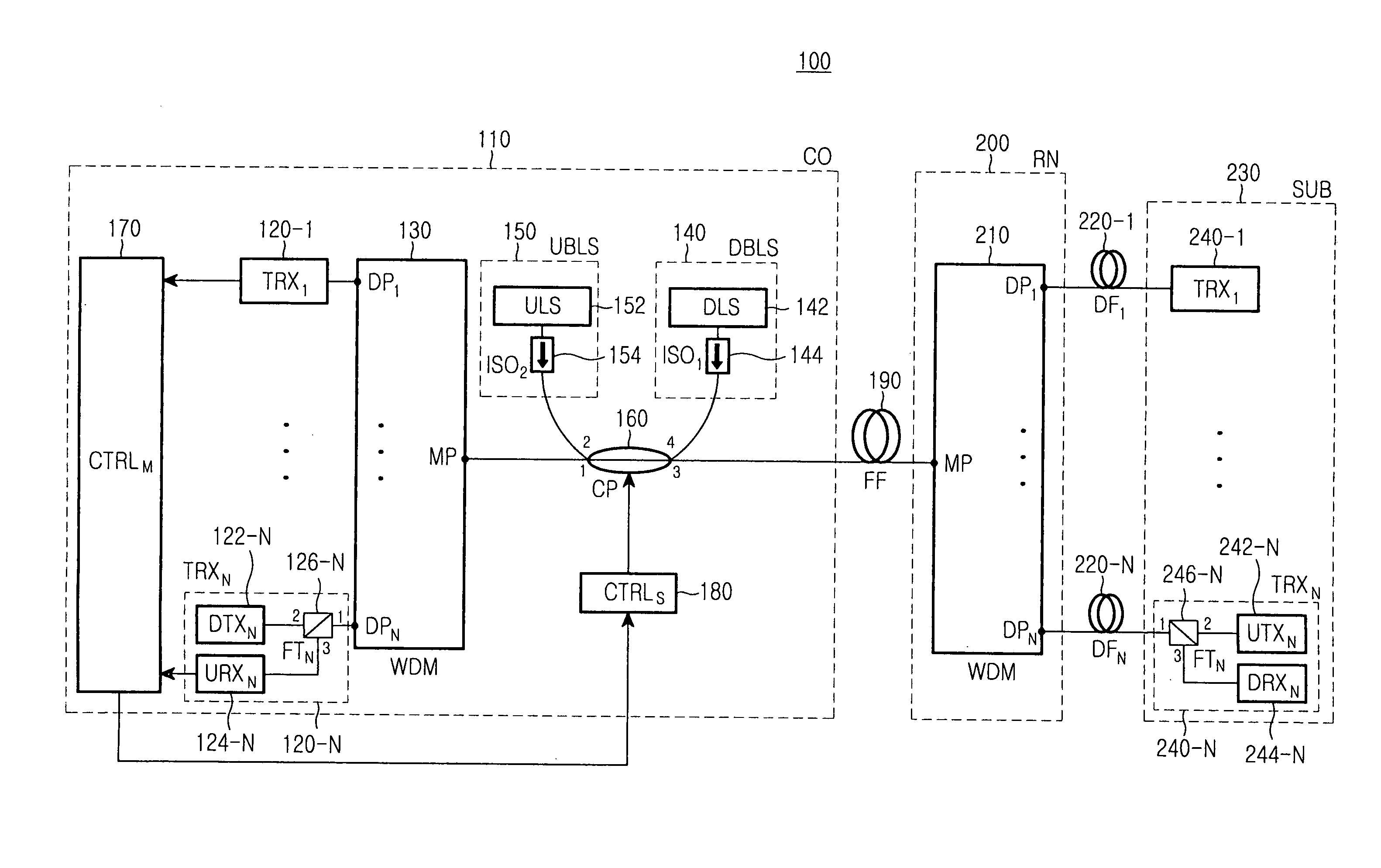
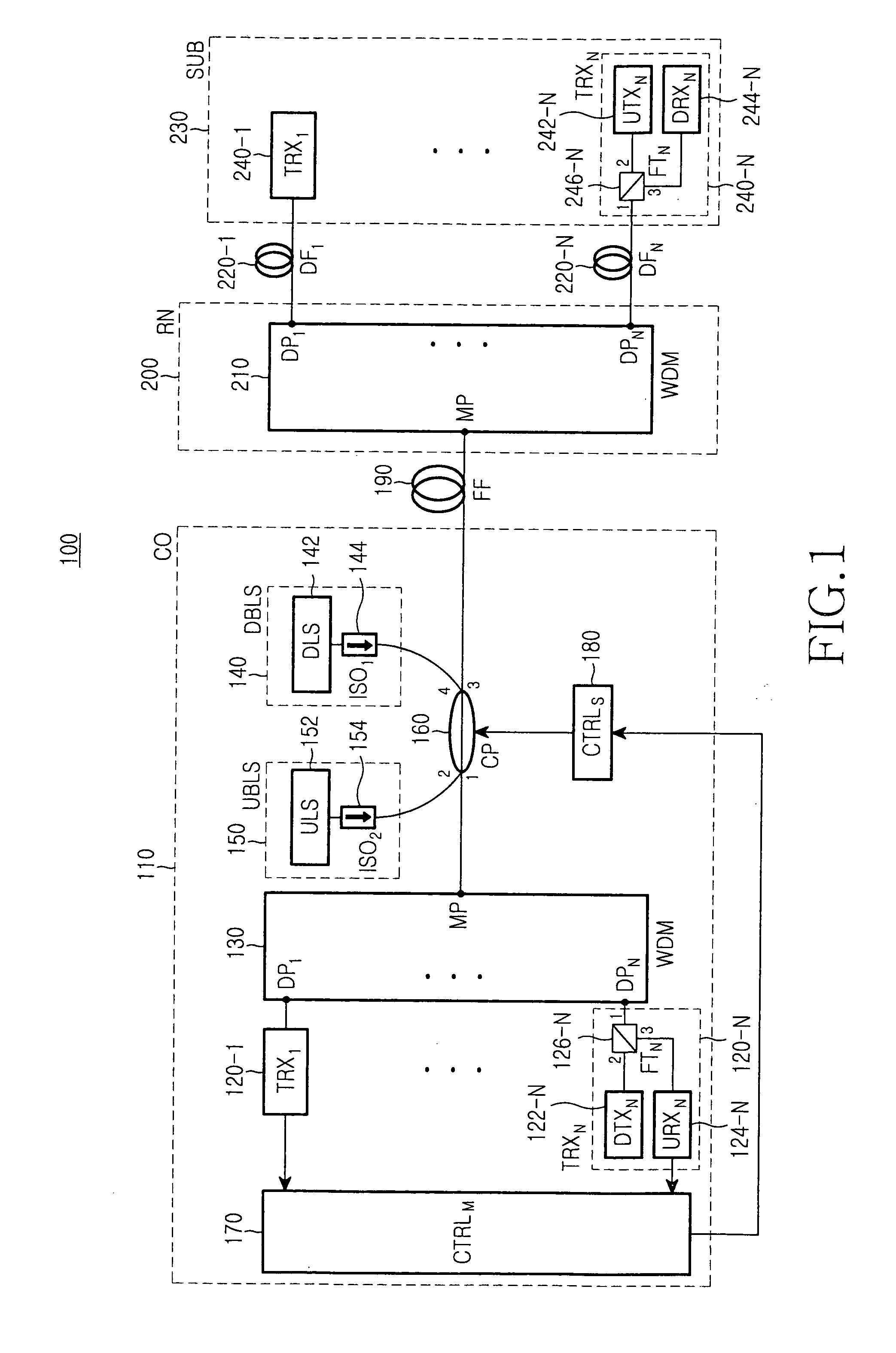
[0018]FIG. 1 is a block diagram illustrating the construction of a wavelength-division-multiplexed passive optical network according to an embodiment of the present invention. As shown, the passive optical network 100 includes a central office (CO) 110, a remote node (RN) 200 connected to the central office 110 through a feeder fiber (FF) 190, and a subscriber-side apparatus (SUB) 230 connected to the remote node 200 through first to Nth distribution fibers (DF) 220-1 to 220-N.

[0019] The central office 110 transmits multiplexed downstream optical signals to the remote node 200 and receives multiplexed upstream optical signals from the remote node 200. The centra...


PUM


Abstract

A wavelength-division-multiplexed light source for transmitting broadband light through a fiber and receiving an optical signal through the fiber is disclosed. The wavelength-division-multiplexed light source includes: a light source for outputting broadband light; and a coupler for outputting the broadband light, which has been input from the light source, to the fiber through cross coupling, and outputting an optical signal, which has been input from the fiber, through bar coupling, based on a predetermined cross coupling ratio, wherein the cross coupling ratio of the coupler is adjusted depending on a power of the optical signal.

Description

CLAIM OF PRIORITY [0001] This application claims the benefit under 35 U.S.C. 119(a) of an application entitled “Wavelength-Division-Multiplexed Light Source And Wavelength-Division-Multiplexed Passive Optical Network Using The Same,” filed in the Korean Intellectual Property Office on Aug. 12, 2005 and assigned Serial No. 2005-74363, the entire contents of which are incorporated herein by reference. BACKGROUND OF THE INVENTION [0002] 1. Field of the Invention [0003] The present invention relates to a wavelength-division-multiplexed light source applicable to a wavelength-division-multiplexed passive optical network (WDM PON). [0004] 2. Description of the Related Art [0005] In order to reduce the maintenance cost for a wavelength-division-multiplexed passive optical network (WDM PON), it is necessary to provide an economical wavelength alignment between the light sources and the wavelength division multiplexers. To achieve this in various networks, in which a wavelength division mult...

Claims


Application Information

Patent Timeline
IPC IPC(8): G02B6/28H04B10/2581
CPCH04J14/02H04J14/0221H04J14/025H04J14/0282H04J14/0246H04J14/0226H04B10/2581
Inventor SHIN, DONG-JAEKIMSHIN, HONG-SEOKPARK, SUNG-BUMJUNG, DAE-KWANGHWANG, SEONG-TAEK
Owner SAMSUNG ELECTRONICS CO LTD
Learn More