Ultrasonic image processing apparatus, ultrasonic diagnostic apparatus, and ultrasonic image processing program

a technology of ultrasonic diagnostic equipment and ultrasonic image processing, applied in the field of visualizing the heart, can solve the problems of shortening information and thickening information that cannot be simultaneously expressed

Active Publication Date: 2007-02-15
TOSHIBA MEDICAL SYST CORP
View PDF11 Cites 23 Cited by
  • Summary
  • Abstract
  • Description
  • Claims
  • Application Information

AI Technical Summary

Benefits of technology

[0007] The present invention has been made in consideration of the above situation, and has as its object to provide an ultrasonic image processing apparatus, ultrasonic diagnostic apparatus, and ultrasonic image processing program which allow simultaneous observation of shortening information even while a short axis view is obtained and observed, and allow simultaneous observation of thickening information even while a long axis view is obtained and observed.

Problems solved by technology

In a conventional ultrasonic diagnostic apparatus, however, the following problems arise.
Therefore, shortening information cannot be simultaneously expressed.
In addition, while a apical long axis approach is obtained and observed by, for example, the tissue Doppler method, thickening information cannot be simultaneously expressed because of a Doppler angle limitation.

Method used


Image

  • Ultrasonic image processing apparatus, ultrasonic diagnostic apparatus, and ultrasonic image processing program
  • Ultrasonic image processing apparatus, ultrasonic diagnostic apparatus, and ultrasonic image processing program
  • Ultrasonic image processing apparatus, ultrasonic diagnostic apparatus, and ultrasonic image processing program

Examples


first embodiment

(First Embodiment)

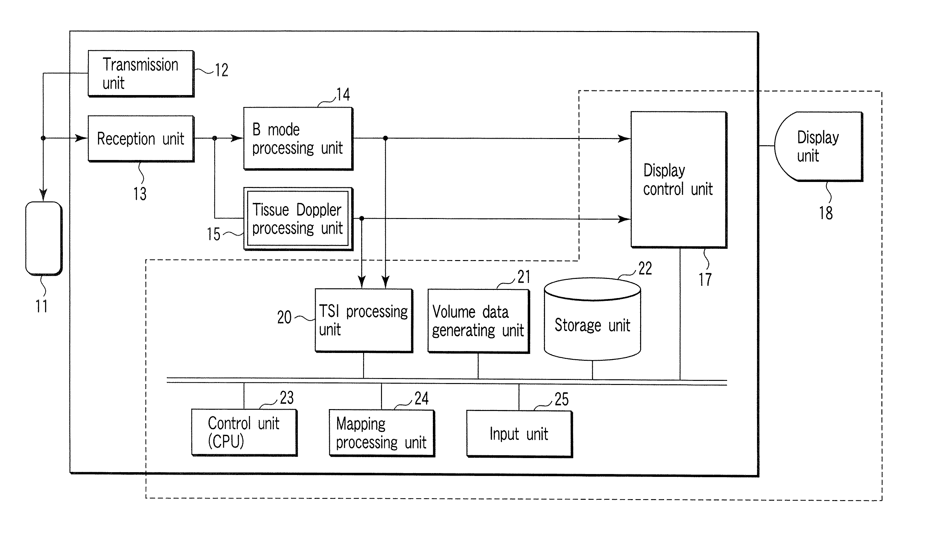
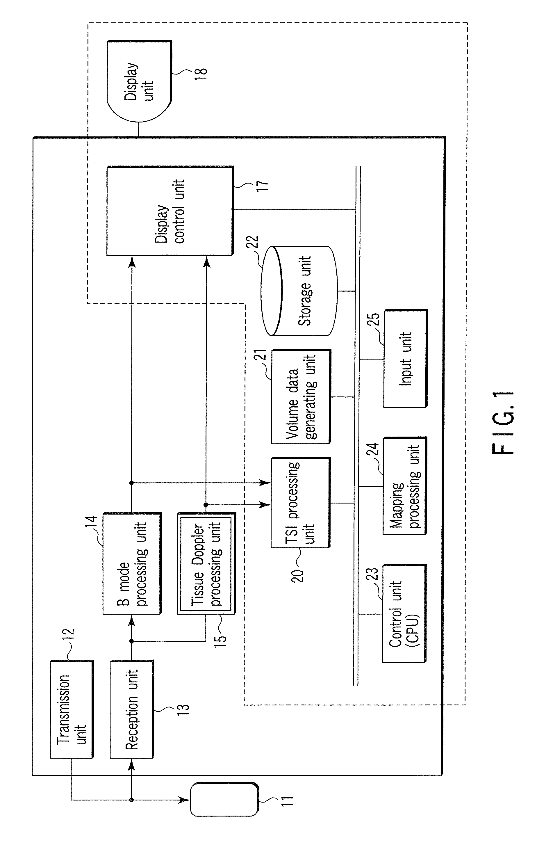
[0041]FIG. 1 is a block diagram showing the arrangement of an ultrasonic diagnostic apparatus 10 according to the first embodiment. The ultrasonic diagnostic apparatus 10 comprises an ultrasonic probe 11, a transmission unit 12, a reception unit 13, a B mode processing unit 14, a tissue Doppler processing unit 15, a display control unit 17, a display unit 18, the TSI processing unit 20, the volume data generating unit 21, a storage unit 22, a control unit (CPU) 23, the mapping processing unit 24, and an input unit 25. Note that when the present invention is applied to the ultrasonic processing apparatus, the constituent elements of the apparatus are those enclosed by the dotted line in FIG. 1.

[0042] The ultrasonic probe 11 generates ultrasonic waves on the basis of a driving signal from the transmission unit 12, and includes a plurality of piezoelectric vibrators which convert reflected waves from a subject to be examined into electrical signals, a matching layer ...

example 1

[0067] The operation of the ultrasonic diagnostic apparatus 10 in orthogonal mapping processing will be described next. Example 1 will exemplify a case wherein the shortening information of a strain on a short axis tomogram is mapped.

[0068]FIG. 12 is a flowchart showing the flow of each process executed in orthogonal mapping processing according to this example. As shown in FIG. 12, first of all, a short axis slice at an arbitrary (desired) position is selected with respect to the volume data of a TSI image (step S1).

[0069] The mapping processing unit 24 acquires shortening information in the long axis direction which is associated with each position of a tissue on a designated short axis slice by using the volume data, and performs color mapping of the information such that a strain intensity is made to correspond to its gray level. With this mapping processing, a mapping image is generated (step S2).

[0070] The display control unit 17 then displays a general ultrasonic image (sh...

example 2

[0071] The operation of the ultrasonic diagnostic apparatus 10 in orthogonal mapping processing will be described next. Example 2 will exemplify a case wherein the thickening information of a strain is mapped on a long axis view.

[0072]FIG. 13 is a flowchart showing the flow of each process to be executed in orthogonal mapping processing according to this example. As shown in FIG. 13, first of all, a long axis slice at an arbitrary (desired) position is selected with respect to the volume data of a TSI image (step S11).

[0073] The mapping processing unit 24 then acquires expansion (thickening information) in a short axis direction which is associated with each position on a tissue exiting on the designated long axis slice, and performs color mapping of the acquired information such that the intensity of a strain is made to correspond to its gray level. With this mapping processing, a mapping image is generated (step S12).

[0074] The display control unit 17 then displays a general ul...


PUM


Abstract

When a two-dimensional tomogram is to be displayed, motion information associated with a direction orthogonal to the tomogram is colored and mapped on the tomogram to be visualized by using the volume data of a TSI image. For example, a mapping image is generated by color-mapping shortening information at each point on a cardiac tissue on a short axis view by using the volume data of the TSI image. Superimposing and displaying the mapping image on the original short axis view makes it possible to simultaneously observe the shortening information even while a short axis view is obtained and observed.

Description

CROSS-REFERENCE TO RELATED APPLICATIONS [0001] This application is based upon and claims the benefit of priority from prior Japanese Patent Application No. 2005-207687, filed Jul. 15, 2005, the entire contents of which are incorporated herein by reference. BACKGROUND OF THE INVENTION [0002] 1. Field of the Invention [0003] The present invention relates to the visualization of a heart by using the TSI (Tissue Strain Imaging) method and, more particularly, to the mapping of the shortening information of the heart in the long axis direction in a contraction phase to a short axis image or the mapping of the thickening information of the heart in the cardiac wall thickness direction to a short axis image. [0004] 2. Description of the Related Art [0005] In general, with regards to a living tissue such as cardiac muscle, it is very important for the diagnosis of the tissue to objectively and quantitatively evaluate the motion or function of the tissue. In image diagnosis using an ultrasoni...

Claims


Application Information

Patent Timeline
Patent Type & Authority Applications(United States)
IPC IPC(8): A61B8/00
CPCA61B8/0883A61B8/14A61B8/463A61B8/483G01S15/8993A61B8/488G01S7/52042G01S7/52071A61B8/485
Inventor ABE, YASUHIKOKAWAGISHI, TETSUYA
Owner TOSHIBA MEDICAL SYST CORP
Why Eureka
Try Eureka