Method and apparatus for assembling exterior automotive vehicle boby components onto an automotive vehicle boby

a technology for automotive vehicles and components, applied in the direction of metal-working machine components, manufacturing tools, transportation and packaging, etc., can solve the problems of building up inaccuracy of the body-in-white, component creation with certain accuracy and tolerance limits, and inability to achieve a rigid assembly

Inactive Publication Date: 2007-02-22
KUKA SYST NORTH AMERICA LLC
View PDF1 Cites 23 Cited by
  • Summary
  • Abstract
  • Description
  • Claims
  • Application Information

AI Technical Summary

Benefits of technology

[0026] According to the present invention, there is provided a method and apparatus for optically establishing a new master locating scheme for an automotive vehicle body, otherwise known as a body-in-white, and thereafter using robotically driven tools precisely assemble components to the body-in-white relative to its new master locating scheme. After the body-in-white has been processed through the framing / welding station(s), work performing tools are robotically positioned with respect to the new master locating scheme and work is performed on the body-in-white to create net or best-fit attachment features adapted to accommodate the attachment of other components and thereby produce a finished vehicle body that meets the flushness and gap specifications between adjacent panels established by the vehicle design team.

Problems solved by technology

This technique interlocks the panels and frame members to each other to the point where they will not separate from each other, but does not achieve a rigid assembly, that is, for example, the side panels may tilt slightly relative to the floor panel.
In those cases where clamping frames are positioned on opposite sides of the body, clearance problems may restrict motion of the welding heads that must pass through the clamping frame before they have access to specific areas of the body to be welded.
It is readily recognized that these conventional assembly techniques include many assembly steps that require parts to be physically stacked on top of one another and then secured to each other by welding, and wherein each component is created with a certain accuracy and tolerance limits.
The small tolerance variations in the primary locating points for locating the underbody combined with the gate fixtures that typically allow some play in the positioning of the panels prior to clamping inherently results in some built-up inaccuracies for the body-in-white.
Also, the repositioning of the framing system in a respot station, again, results in an additional positional tolerance variation inherently creating additional inaccuracies for the location of the various panels with respect to each other.
The resulting structure incorporates each of the modules by locating each module at a net position thereby reducing the overall built up tolerance for the complete assembly.
Although a majority of the prior art has recognized the existence of built in inaccuracies in the building of automotive bodies, by the stacking of tolerances between adjacent components, resulting in unacceptable mating conditions, little has been said in the prior art regarding those inherent inaccuracies of the various processes themselves.
However, if any misalignment exists between associated components or panels, the spot welding that creates the weld will tend to displace the component or panel from the desired assembly location to some unknown position relative to design-intent or an established X, Y and Z Cartesian coordinate systems.
Accordingly, although modular construction may be suggested to avoid tolerance build up, the clamping of the modular components into the rigid fixtures can easily result in stretching or compression points in the vehicle body that may cause stress induced cracks or other deficiencies especially after the weld is created.
Thus, the problem with existing fixtures whether they are framing fixtures or tooling to assemble modular components is that these assemblies are assembled with internal stresses that can cause deformities in the assembled sheet metal resulting in failures to the assemblies when in use, i.e. popped welds, etc.
Further, after clamping these components or panels into the rigid fixtures, thousands of welds are produced resulting in additional stresses as well as distortion due to the heat and pressure associated with the use of welding guns leading to the conclusion that after the body-in-white has been processed in the appropriate framing and welding stations, it is impossible to know the final location of the surfaces as well as any targets, master holes or whatever else is attached to the panels before the welding operations occur.
Because of the tolerance variations of the body-in-white, excessive gapping may result between panels or between the door and a door opening.
However, due to the distortions of the body-in-white as a result of the assembly / welding processes, it was still necessary to provide a slip plane in order to permanently attach the outer body attachment panels for the purpose of obtaining proper gaps and correct flushness between adjacent panels as well as alignment of feature lines between adjacent panels.
Obviously, when using this sophisticated equipment in a production environment many problems can surface including but not limited to, environmental debris as a result of welding operations, sensitivity problems with the equipment, technical support team necessary to monitor equipment, etc.

Method used


Image

  • Method and apparatus for assembling exterior automotive vehicle boby components onto an automotive vehicle boby
  • Method and apparatus for assembling exterior automotive vehicle boby components onto an automotive vehicle boby
  • Method and apparatus for assembling exterior automotive vehicle boby components onto an automotive vehicle boby

Examples


Embodiment Construction

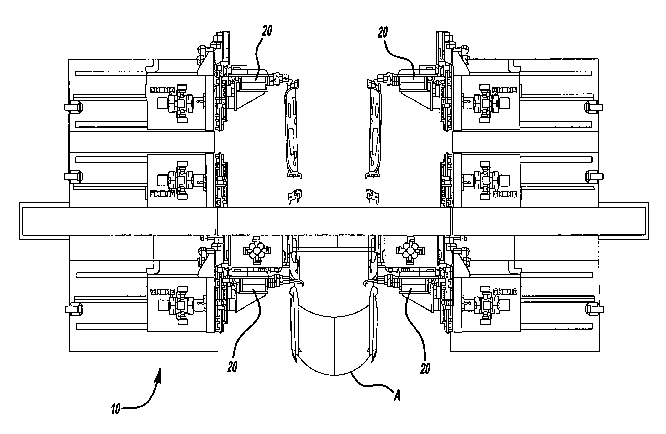
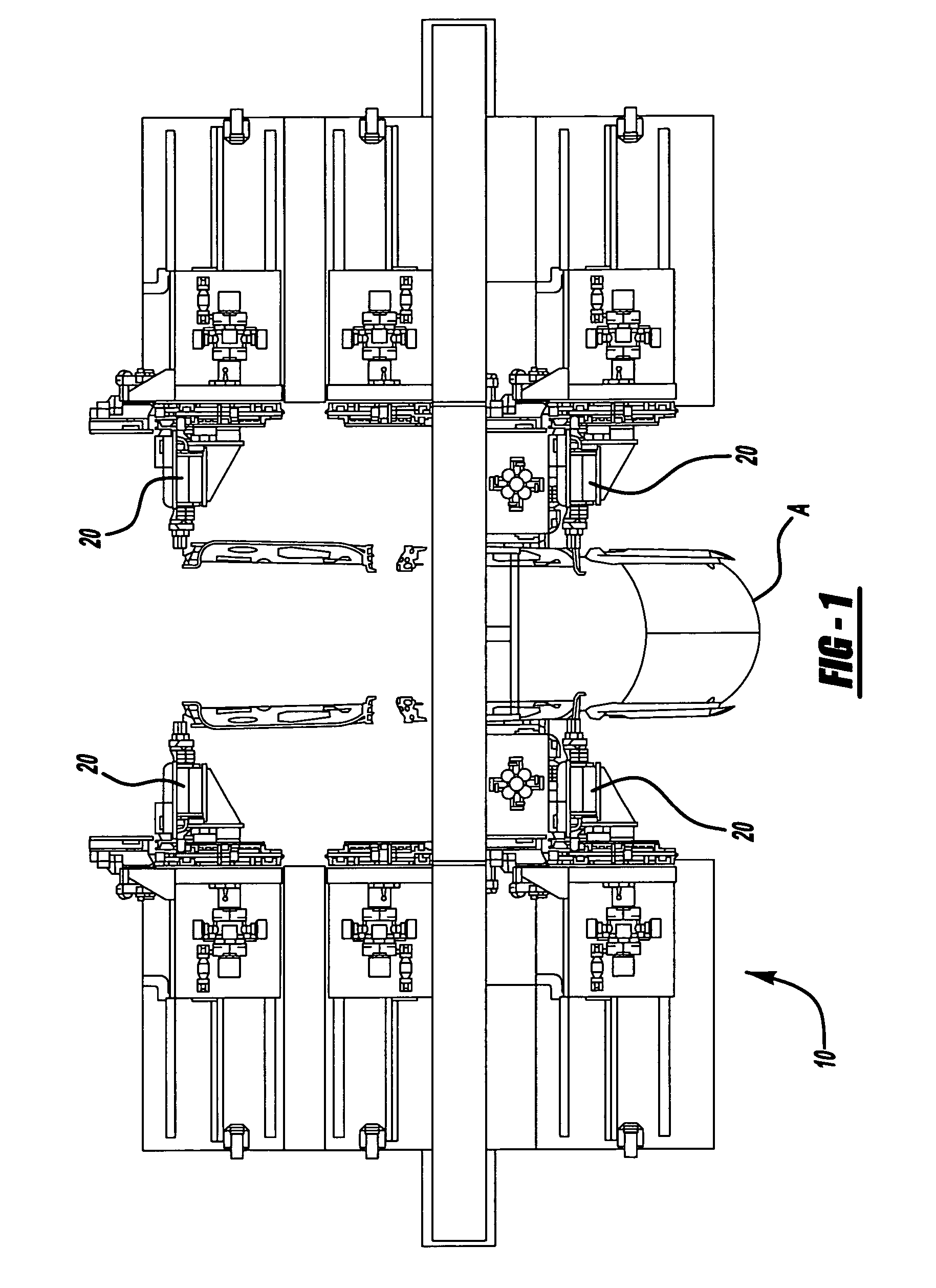
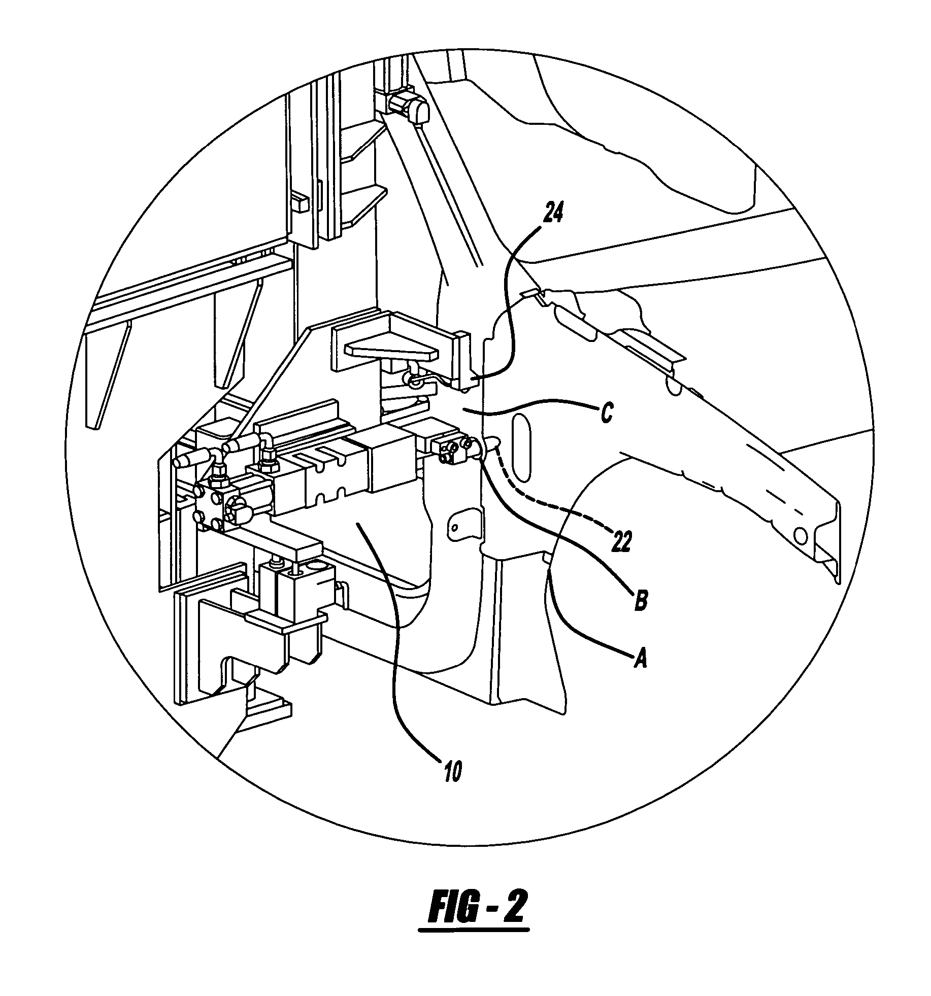
[0064] Generally shown in the figures, is a method and apparatus for utilizing position detection apparatuses to locate primary locating points on a vehicle body, also known as a body-in-white. In accordance with the present invention, after the primary locating points have been located and the position detecting apparatus have been locked in place, a set of locator pins and input sockets, one of which is attached to the position detecting apparatus and the other of which is attached to a balancing lever mechanism fixed to the gantry spanning the production line, is used to balance out or average the deviation of the primary locating points in cross-car, fore / aft and up / down directions of the actual body-in-white as built, from design-intent positions. This average or balancing out would obviously not be required if the processing of the body-in-white resulted in all panels and attachment points being actually located at design-intent position after the vehicle body was processed th...


PUM

PropertyMeasurementUnit
imprecise distanceaaaaaaaaaa
structurally rigidaaaaaaaaaa
structural rigidityaaaaaaaaaa

Abstract

The present invention generally relates to a method and programmable apparatus for the assembly of body components to an automotive body that has undergone a progressive series of framing and welding steps so as to produce a structurally rigid body frame, termed a body-in-white. More specifically, this invention relates to creating a new net locating scheme (X, Y and Z Cartesian coordinate system) for a body-in-white to direct associated tooling to create net attachment features on a rigid body frame with respect to a new net locating scheme so that components may be attached to a automotive body at a net location eliminating the need for any slip plane attachment techniques.

Description

CROSS-REFERENCES TO RELATED APPLICATIONS [0001] This application is a continuation-in-part application which claims the benefit of copending nonprovisional U.S. patent application Ser. No. 10 / 779,185, filed on Feb. 16, 2004 which was a continuation-in-part application claiming the benefit of U.S. patent application Ser. No. 10 / 146,780 filed May 16, 2002, which issued on Feb. 17, 2004 as U.S. Pat. No. 6,691,392, which claims the benefit of U.S. provisional patent application Ser. No. 60 / 291,522 filed May 16, 2001.FEDERALLY SPONSORED RESEARCH OR DEVELOPMENT [0002] Not applicable. REFERENCE TO A MICROFICHE APPENDIX [0003] Not applicable. BACKGROUND OF THE INVENTION [0004] 1. Field of the Invention [0005] The present invention generally relates to a method and apparatus for the assembly of body components to an automotive body that has undergone a progressive series of positioning and welding steps so as to produce a structurally rigid body frame, termed a body-in-white. More specifical...

Claims


Application Information

Patent Timeline
Patent Type & Authority Applications(United States)
IPC IPC(8): B23Q17/00B21D39/03
CPCB62D65/06B62D65/18Y10T29/4978Y10T29/49778Y10T29/53022Y10T29/53048Y10T29/49902Y10T29/49828Y10T29/49895Y10T29/49829
Inventor SAVOY, MARK A.
Owner KUKA SYST NORTH AMERICA LLC
Why Eureka
Try Eureka