Refrigerant cycle device with ejector
- Summary
- Abstract
- Description
- Claims
- Application Information
AI Technical Summary
Benefits of technology
Problems solved by technology
Method used
Image

Examples
first embodiment
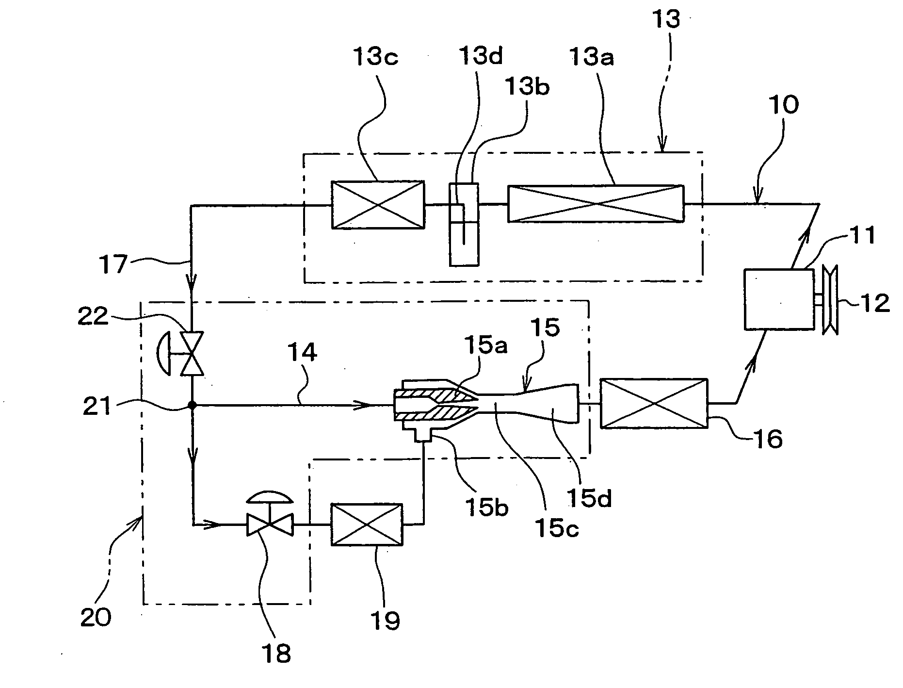
[0025]FIG. 1 shows an example in which a refrigerant cycle device 10 according to the first embodiment of the invention is applied to a refrigeration system for a vehicle. In the refrigerant cycle device 10 of the embodiment, a compressor 11 for drawing and compressing refrigerant is rotatably driven by an engine for a traveling vehicle (not shown) via a pulley 12, a belt, or the like.
[0026] The compressor 11 may be either a variable displacement compressor capable of adjusting a refrigerant discharge capability by a change in discharge capacitance, or a fixed displacement compressor adapted to adjust a refrigerant discharge capability by changing an operating ratio of the compressor using disengagement of an electromagnetic clutch. For an electric compressor used as the compressor 11, a refrigerant discharge capability can be adjusted by regulation of the number of revolutions of an electric motor.
[0027] A supercooling device-integrated condenser 13 is disposed on a refrigerant d...
second embodiment
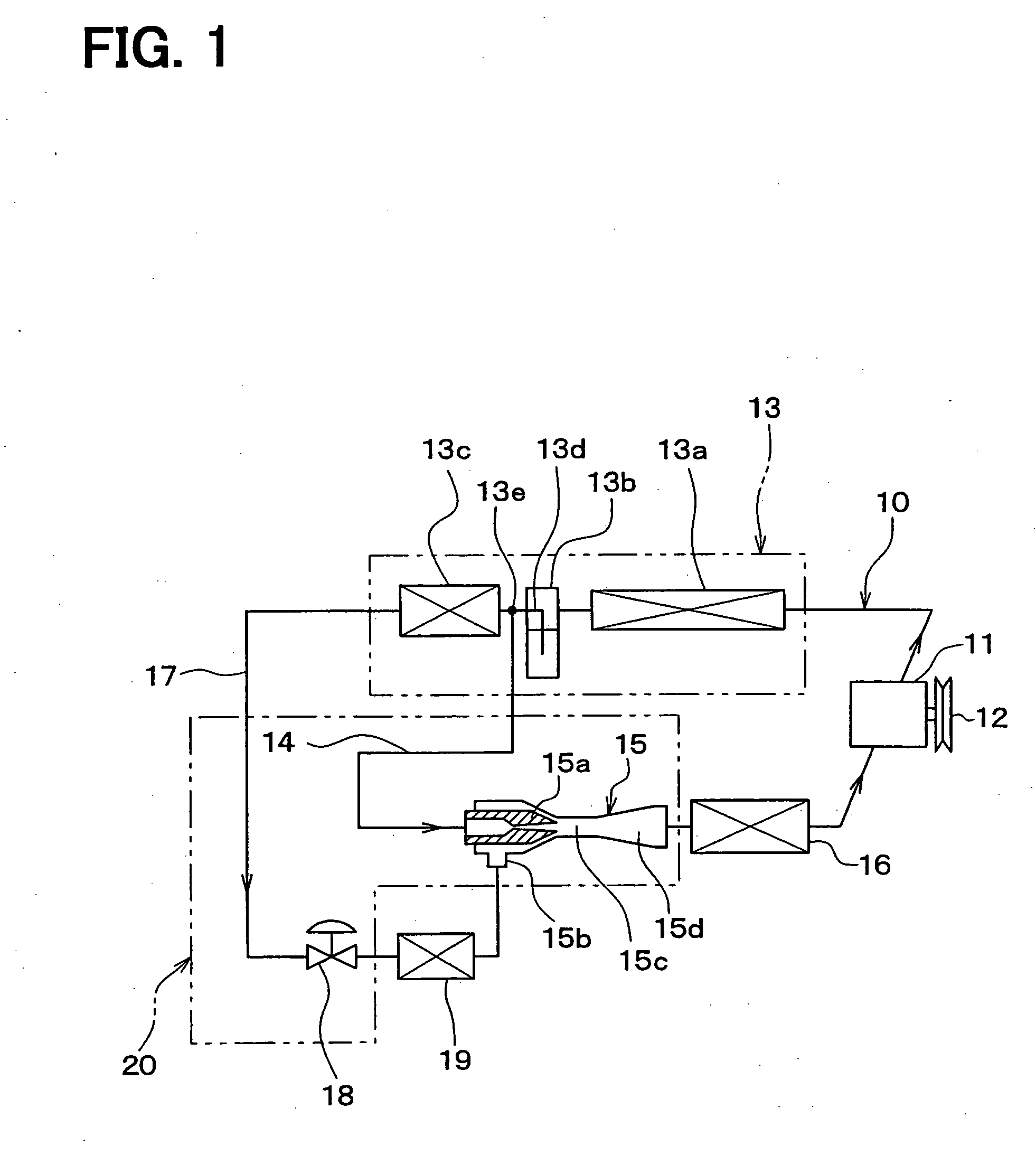
[0055] A refrigerant cycle device 10 of the second embodiment will be now described with reference to FIG. 2.
[0056] In the above-described first embodiment, the branch point 13e is provided in the liquid-phase refrigerant outlet path 13d between the vapor-liquid separator 13b and the supercooling device 13c, and the saturated liquid-phase refrigerant flow is branched into the two streams at the branch point 13e, such that the saturated liquid-phase refrigerant flowing out of the vapor-liquid separator 13b flows into the ejector 15 via the refrigerant path 14. In the second embodiment, a branch point 21 is set in the refrigerant path 17 of the outlet side of the supercooling device 13c as shown in FIG. 2, and the supercooled liquid-phase refrigerant flows from the branch point 21 into the nozzle 15a of the ejector 15 via the refrigerant path 14.
[0057] According to the second embodiment, the liquid-phase refrigerant supercooled by the supercooling device 13c is decompressed by both ...
third embodiment
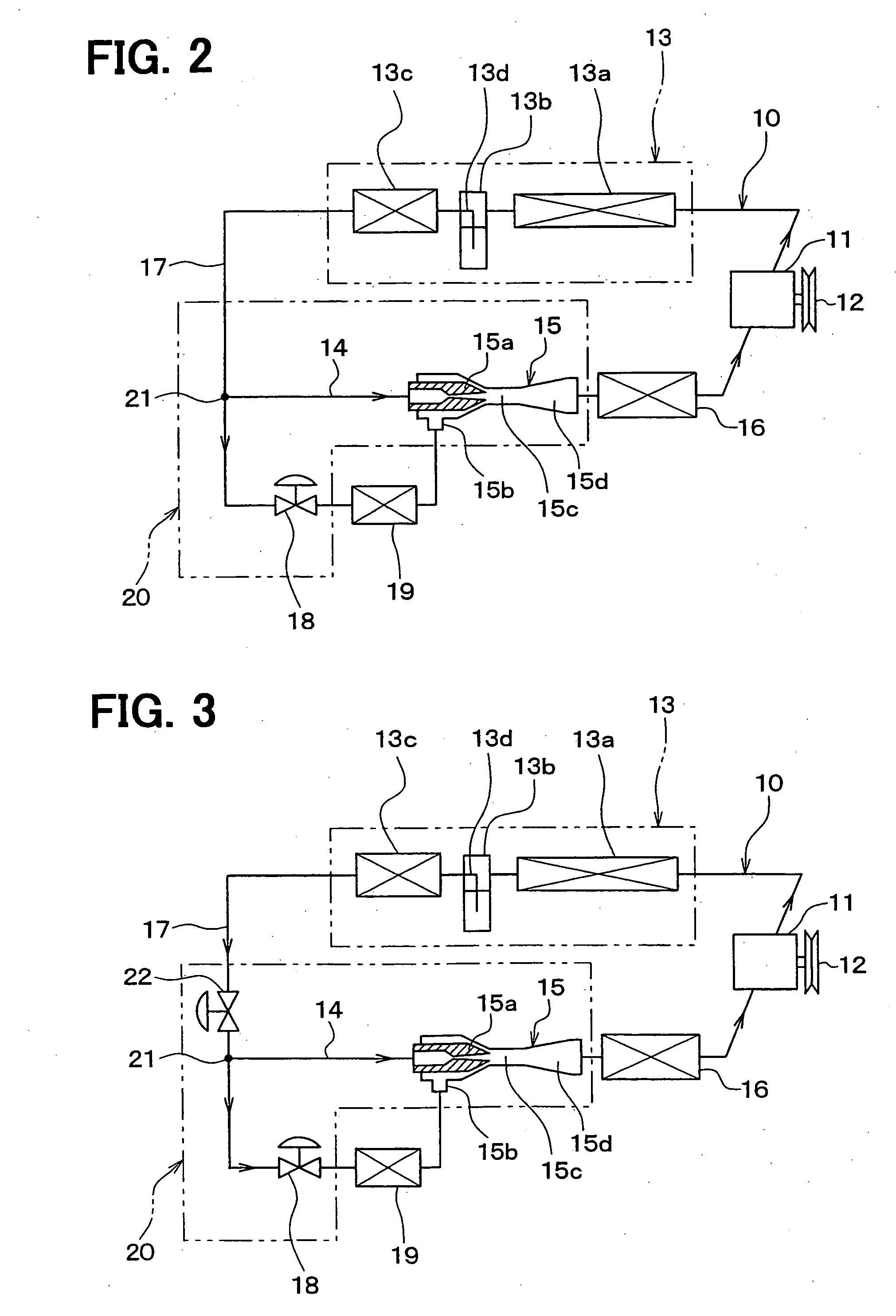
[0059]FIG. 3 shows a refrigerant cycle device 10 of the third embodiment, in which a throttle mechanism 22 is added to the cycle structure of the second embodiment at an upstream side of the branch point 21 in the refrigerant path 17. As the throttle mechanism 22, either a fixed throttle or a variable throttle may be used. In the third embodiment, three of the throttle mechanism 18, the throttle mechanism 22 and the ejector 15 can be integrally formed as a decompression module 20.
[0060] When a thermal expansion valve or an electric expansion valve is used as an example of the throttle mechanism 22 to control the degree of superheat of the refrigerant at the outlet of the first evaporator 16 to a predetermined value, liquid refrigerant returning to the compressor 11 can be prevented reliably. In the third embodiment, the other parts can be made similarly to those of the above-described second embodiment.
PUM
 Abstract
Description
Claims
Application Information
 - Generate Ideas
- Intellectual Property
- Life Sciences
- Materials
- Tech Scout
- Unparalleled Data Quality
- Higher Quality Content
- 60% Fewer Hallucinations
Browse by: Latest US Patents, China's latest patents, Technical Efficacy Thesaurus, Application Domain, Technology Topic, Popular Technical Reports.
© 2025 PatSnap. All rights reserved.Legal|Privacy policy|Modern Slavery Act Transparency Statement|Sitemap|About US| Contact US: help@patsnap.com