
Air filtration system

a technology of air filtration and filter body, which is applied in the direction of electric supply techniques, lighting and heating apparatus, heating types, etc., can solve the problems of filter efficiency dropping and the type of filter generally requiring frequent maintenance, so as to reduce the chance of contamination, easy to remove for cleaning or replacement, and minimize the effect of chan

Active Publication Date: 2007-02-22
TRANE INT INC
View PDF33 Cites 48 Cited by
  • Summary
  • Abstract
  • Description
  • Claims
  • Application Information

AI Technical Summary

Benefits of technology

The present invention provides an improved air filtration system for use in indoor spaces, including residential buildings. The system includes a frame for supporting various filter units, including an intense field dielectric air filtration system. The filter units interlock with each other to prevent air flow bypassing the filters and are provided with electrode contact members which connect with conductors which connect with opposite sides of the filter units. The system also includes a display, switches, and a control system for easy cleaning and replacement of the filter components. The invention provides a compact array of field charging electrodes at the air inlet and a unique arrangement of filter media to induce electrical charges on or across the surfaces of dielectric sheets or elements to create an intense electric field that results in high efficiency particle collection. The control system provides a fully regulated high voltage power supply with circuitry that minimizes the risk of harmful electrical discharge.

Problems solved by technology

As dirt accumulates on the filter plates, the efficiency of the filter drops and thus this type of filter generally requires frequent maintenance.
The implementation of intense field dielectric filters has, however, posed certain problems in the development of a practical, cost effective filter system that may be incorporated in HVAC equipment, attached as an add-on to HVAC equipment and utilized as a stand-alone filter interposed in an air flow duct, for example.

Method used


Image

  • Air filtration system
  • Air filtration system
  • Air filtration system

Examples


Embodiment Construction

[0034] In the description which follows, like parts are marked throughout the specification and drawing with the same reference numerals, respectively. The drawing figures are not necessarily to scale and certain features may be shown in schematic or somewhat generalized form in the interest of clarity and conciseness.

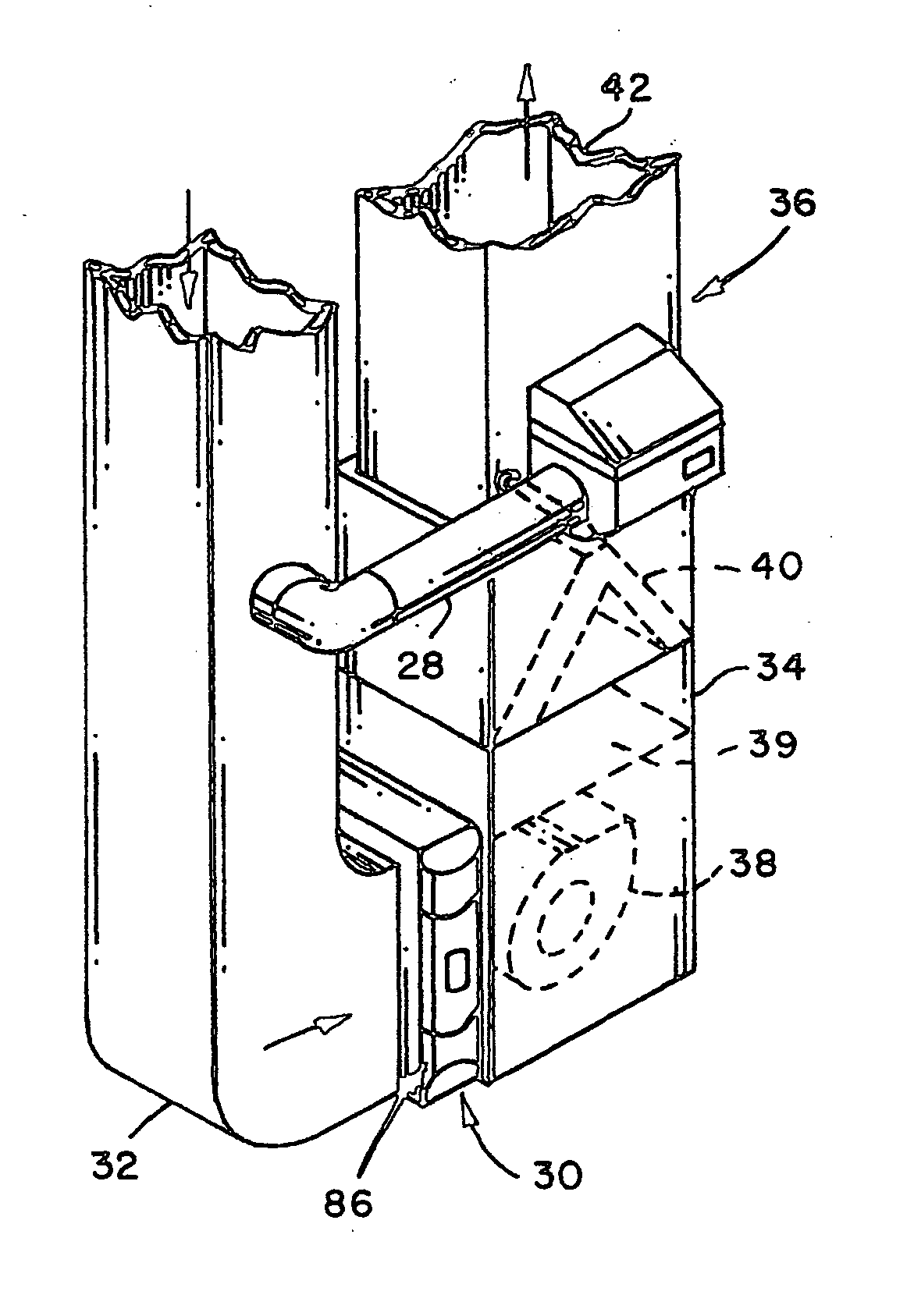
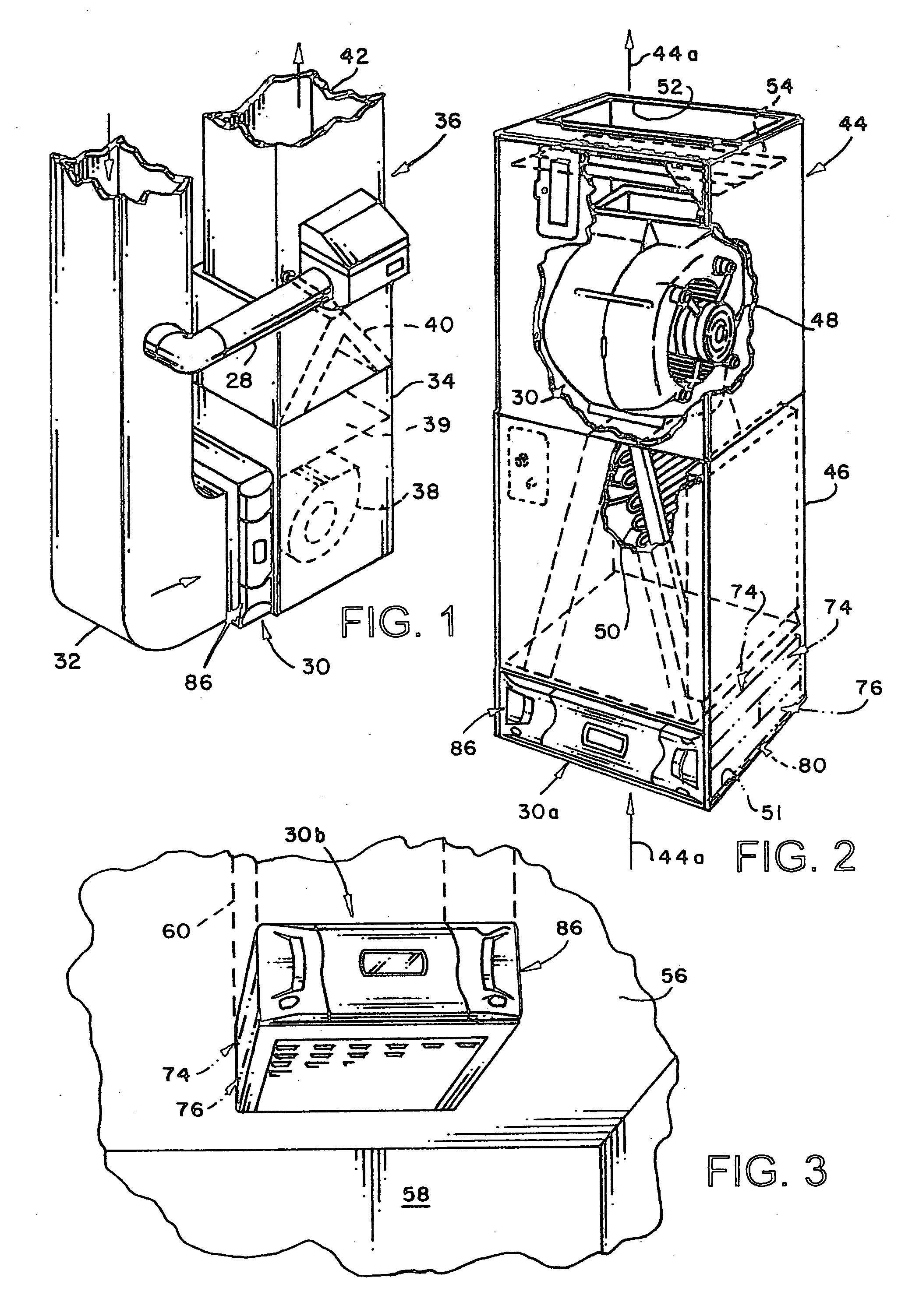
[0035] Referring now to FIG. 1, there is illustrated an embodiment of the invention comprising an intense field dielectric air filtration system, generally designated by the numeral 30. The filtration system 30 is shown interposed in an air flowpath from a return air duct 32 leading to the interior of a cabinet 34 for an air conditioning unit 36. The air conditioning unit 36 includes conventional components such as a motor driven fan 38, a furnace heat exchanger 39 and a heat exchanger 40 which may be part of a vapor compression air conditioning system and which may or may not be reversible so that the air conditioning unit 36 may be capable of providing one, or the o...


PUM


Abstract

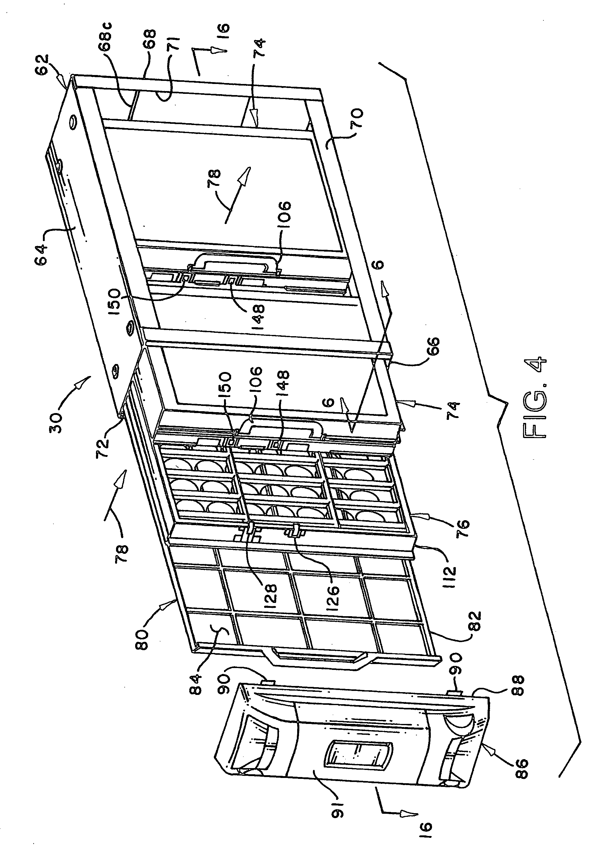
An air filtration system includable in and for HVAC equipment includes one or more intense field dielectric filter units and a field charging unit retained in a support structure or cabinet by a removable door which includes control circuitry and contactors engageable with corresponding contact members on a filter unit and the field charging unit for supplying high voltage DC potential to the respective units. Each filter unit includes a filter core comprising a stacked array of filter elements formed of dielectric sheets interconnected by elongated spaced apart ribs forming flow passages. The field charging unit and the filter units are removable from the support or cabinet for cleaning or replacement by opening or removing the door. An interlock switch and a field shorting mechanism are actuated during servicing or replacement of the system components.

Description

BACKGROUND OF THE INVENTION [0001] The filtration of air being circulated by and through heating, ventilating and air conditioning (HVAC) equipment has become an increasingly desirable and necessary process. Historically, air filtration systems and devices associated with HVAC equipment have been provided to maintain the equipment in a state of cleanliness and high efficiency. However, in recent years, the filtration of indoor air has become important to maintain and improve human health and to keep interior rooms and furnishings more clean. [0002] Air filter selection criteria includes filter dirt collection “efficiency”, air pressure drop across the filter, available space for the filter system, dirt or dust holding capacity of the system and, of course, initial and replacement costs. With regard to the filtration of indoor air in residential dwellings and commercial facilities, there has been an increasing need for filters which will suitably perform particle filtration. Conventi...

Claims


Application Information

Patent Timeline
Patent Type & Authority Applications(United States)
IPC IPC(8): B03C3/12B03C3/155
CPCB03C3/025B03C3/09B03C3/72B03C3/86F24F2003/1682B03C2201/28F24F3/166F24F2003/1635B03C3/88Y02A50/20F24F8/194F24F8/192F24F8/30
Inventor BIAS, LARRY STEPHENFIELD, JAY ERNESTSALVAGE, SCOTT ANTHONYSMITH, SHANNON LEIGHVENDT, STEPHEN J.WOODRUFF, MARK D.
Owner TRANE INT INC
Learn More