Well chemical treatment utilizing plunger lift delivery system with chemically improved plunger seal

a technology of chemical treatment and plunger seal, which is applied in the direction of sealing/packing, fluid removal, borehole/well accessories, etc., to achieve the effect of increasing the efficiency of chemical treatmen

Inactive Publication Date: 2007-02-22
CONOCOPHILLIPS CO
View PDF25 Cites 52 Cited by
  • Summary
  • Abstract
  • Description
  • Claims
  • Application Information

AI Technical Summary

Benefits of technology

[0036] Also, the dispenser may include an extension or standoff section which allows the receptacle holding the treatment chemical to be positioned below the lower end of the tubing when the plunger assemb...

Problems solved by technology

In addition, it will fall to the bottom of the w...

Method used


Image

  • Well chemical treatment utilizing plunger lift delivery system with chemically improved plunger seal
  • Well chemical treatment utilizing plunger lift delivery system with chemically improved plunger seal
  • Well chemical treatment utilizing plunger lift delivery system with chemically improved plunger seal

Examples


Embodiment Construction

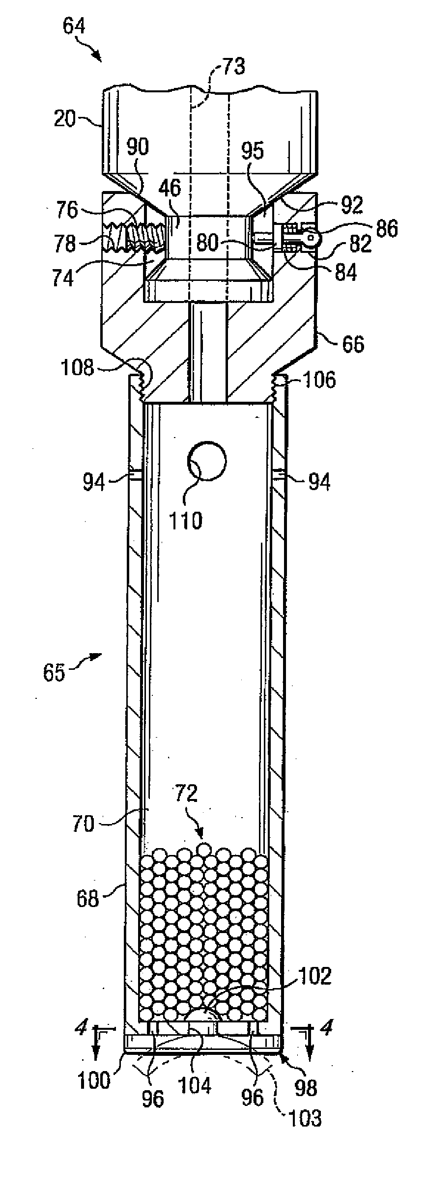
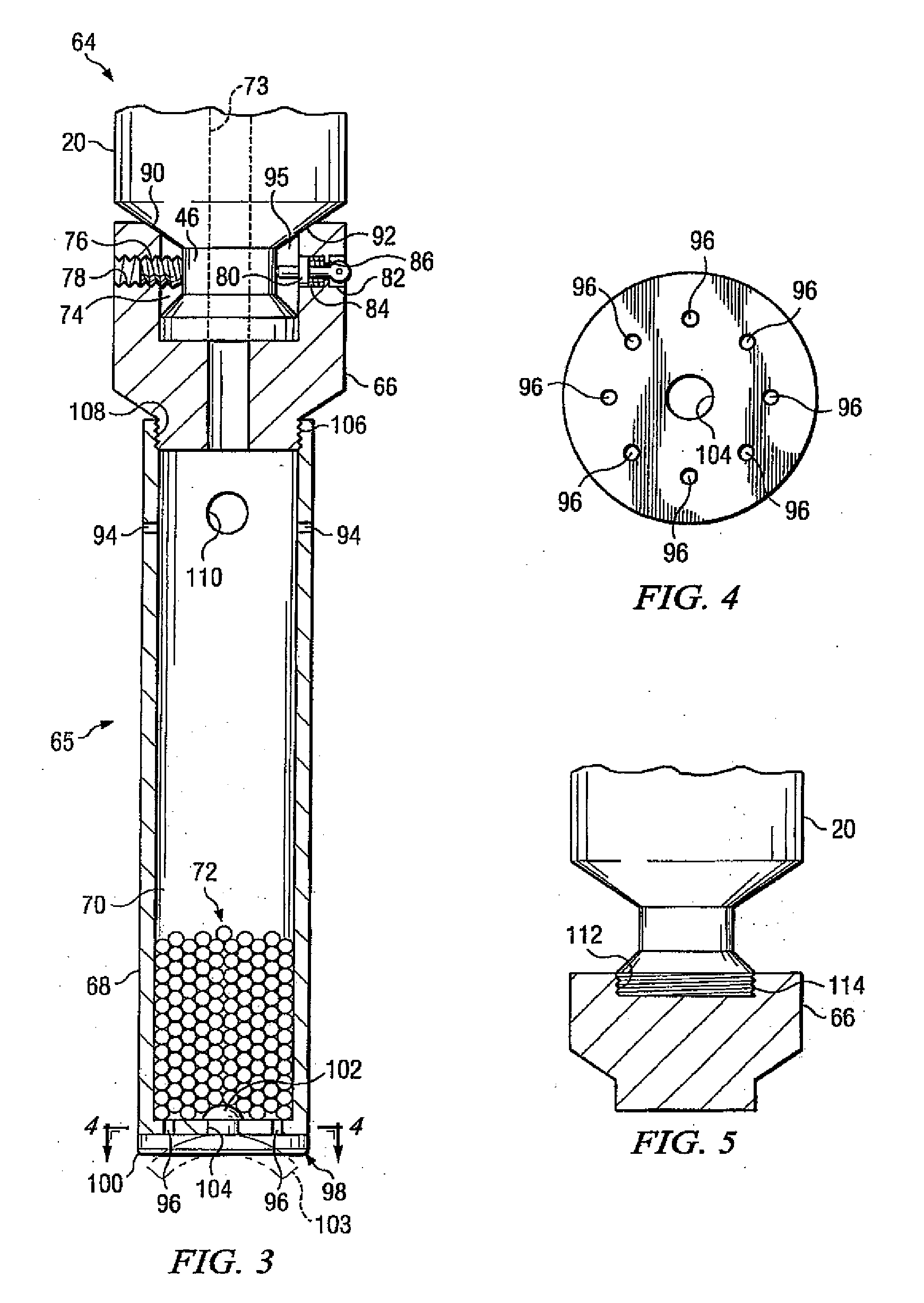
[0040] For purposes of background, an abbreviated discussion of the plunger lift technique will be presented. Those skilled in the art will recognize that there are many variations which have been used in connection with the lift technique and system which is described. While the discussion will focus on gas producing plunger lift wells, the method of the present invention is also suited for use on oil producing wells, and can be modified for variations of the described lift system. Further, those skilled in the art will appreciate that the present invention need not be used to the exclusion of other chemical treatment methods. Costs and other considerations can result in the use of the present invention together with other treatment methods.

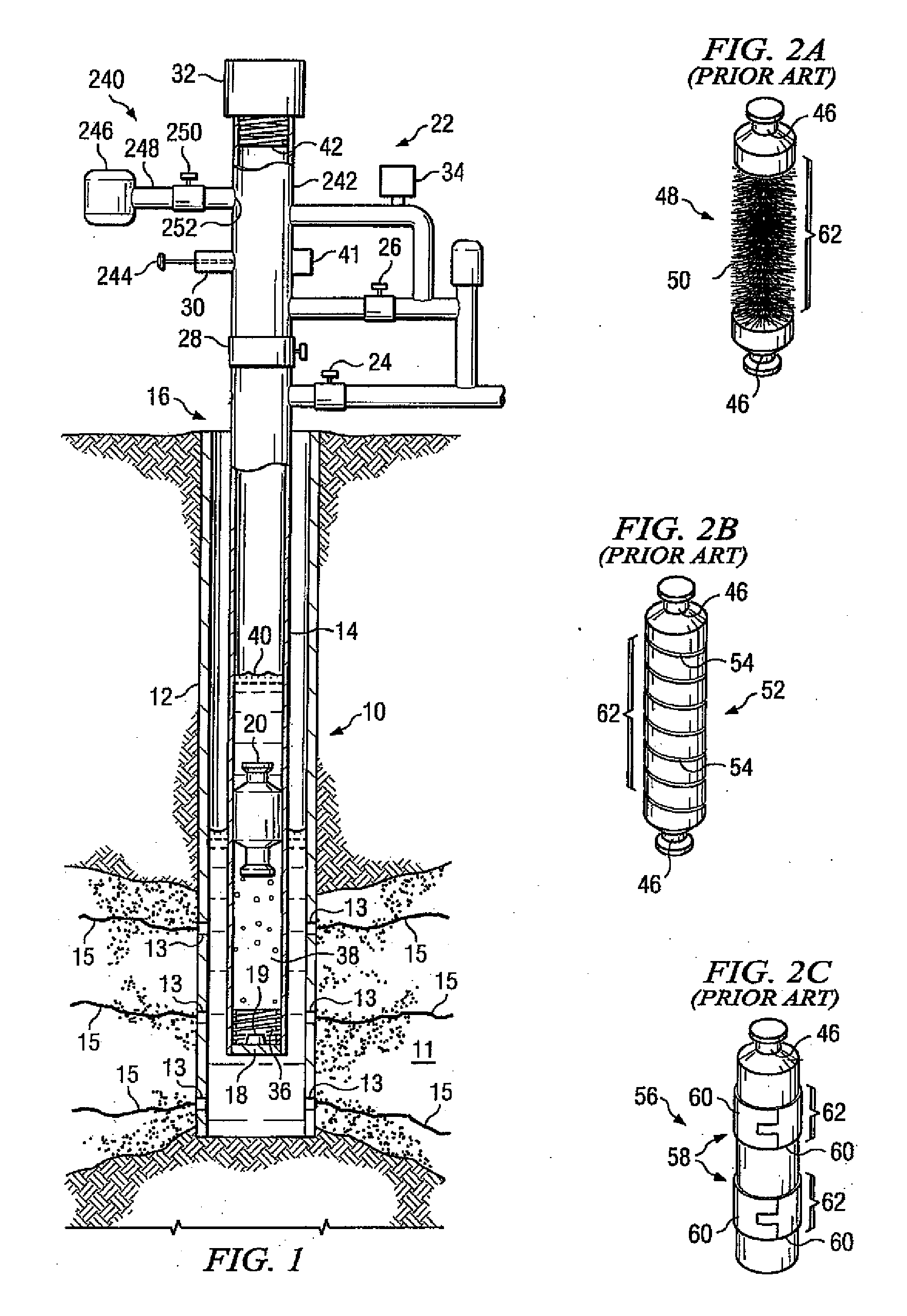
[0041] With reference to FIG. 1, the gas well 17 will have a wellbore 10 located within petroleum-bearing formation 11 and which typically contains a casing 12 either throughout the entire well or a portion of the wellbore. Extending through a ...


PUM


Abstract

An apparatus incorporating a chemical seal and method for removing fluids from a well is disclosed. The chemical seal is created by a foaming agent which, when in the presence of gas and fluids present in the well, and when agitated by the apparatus, creates foam between the apparatus and the walls of the well in which it operates. The foam improves the seal between the apparatus and the inner wall of the well, improving the efficiency of the apparatus in lifting fluids from the well. Furthermore, the chemical seal improves the distribution of treatment chemicals within the well as it reduces liquid flowback. Automatic recharging or reapplication of the foaming agent and/or treatment chemicals to the apparatus can be accomplished with a chemical application assembly associated with the well.

Description

[0001] This is a continuation-in-part application of U.S. patent application Ser. No. 10 / 630,292 filed on Jul. 30, 2003.TECHNICAL FIELD [0002] The present invention relates to petroleum production and has significant application to wells which use plunger lift systems to aid in production from the well. In particular, the invention relates to an improved seal between a plunger used in a plunger lift system and the inside surface of the tubing in which the plunger travels. BACKGROUND OF THE INVENTION [0003] This invention relates to production from petroleum wells, and in particular, an improvement to the efficiency of plunger lift techniques and an improvement to the efficiency of chemical treatment of wells using plunger lift techniques. The invention will find use in wells which produce either gas or oil, including those using enhanced production techniques such as artificial gas lift. It is anticipated that the invention will find the greatest use in low producing or “stripper” w...

Claims


Application Information

Patent Timeline
IPC IPC(8): E21B43/00E21B27/02E21B37/06E21B43/12
CPCE21B27/02E21B33/068E21B43/25E21B43/121E21B37/06
Inventor WILSON, DENNIS RAY
Owner CONOCOPHILLIPS CO
Why Eureka
Try Eureka