Control unit and optical disk drive including the control unit

a technology of optical disk drive and control unit, which is applied in the direction of recording information storage, disposition/mounting of heads, instruments, etc., to achieve the effect of reducing working distance, avoiding collisions, and flexible control of focal points

Active Publication Date: 2007-02-22
PANASONIC CORP
View PDF2 Cites 4 Cited by
  • Summary
  • Abstract
  • Description
  • Claims
  • Application Information

AI Technical Summary

Benefits of technology

[0024] According to the present invention, a position control signal that changes the positions of a converging section at a velocity that is variable depending on where the converging section is located is output, thereby shifting the focal point of light to a focus controllable range. After that, a focus control signal that keeps the focal point of the light within the focus controllable range is output. By shifting the focal point at a velocity that varies according to the position of the converging section, the focal point can be controlled more flexibly compared to the situation where the focal point is always shifted at the same velocity. As a result, an appropriate distance can be maintained between the objective lens that determines the focal point and the disk and their collision can be avoided. Among other things, even when the NA of an optical system is increased and the working distance is decreased to realize high-density recording, the collision can also be avoided. That is why this technique can be used particularly effectively in an optical disk drive for a mobile device that is easily subject to impacts and vibrations.

Problems solved by technology

However, since the objective lens is located close to the disk, the objective lens might contact with, or collide against, the disk loaded or a member of the disk drive while no focus control is being performed.

Method used


Image

  • Control unit and optical disk drive including the control unit
  • Control unit and optical disk drive including the control unit
  • Control unit and optical disk drive including the control unit

Examples


Embodiment Construction

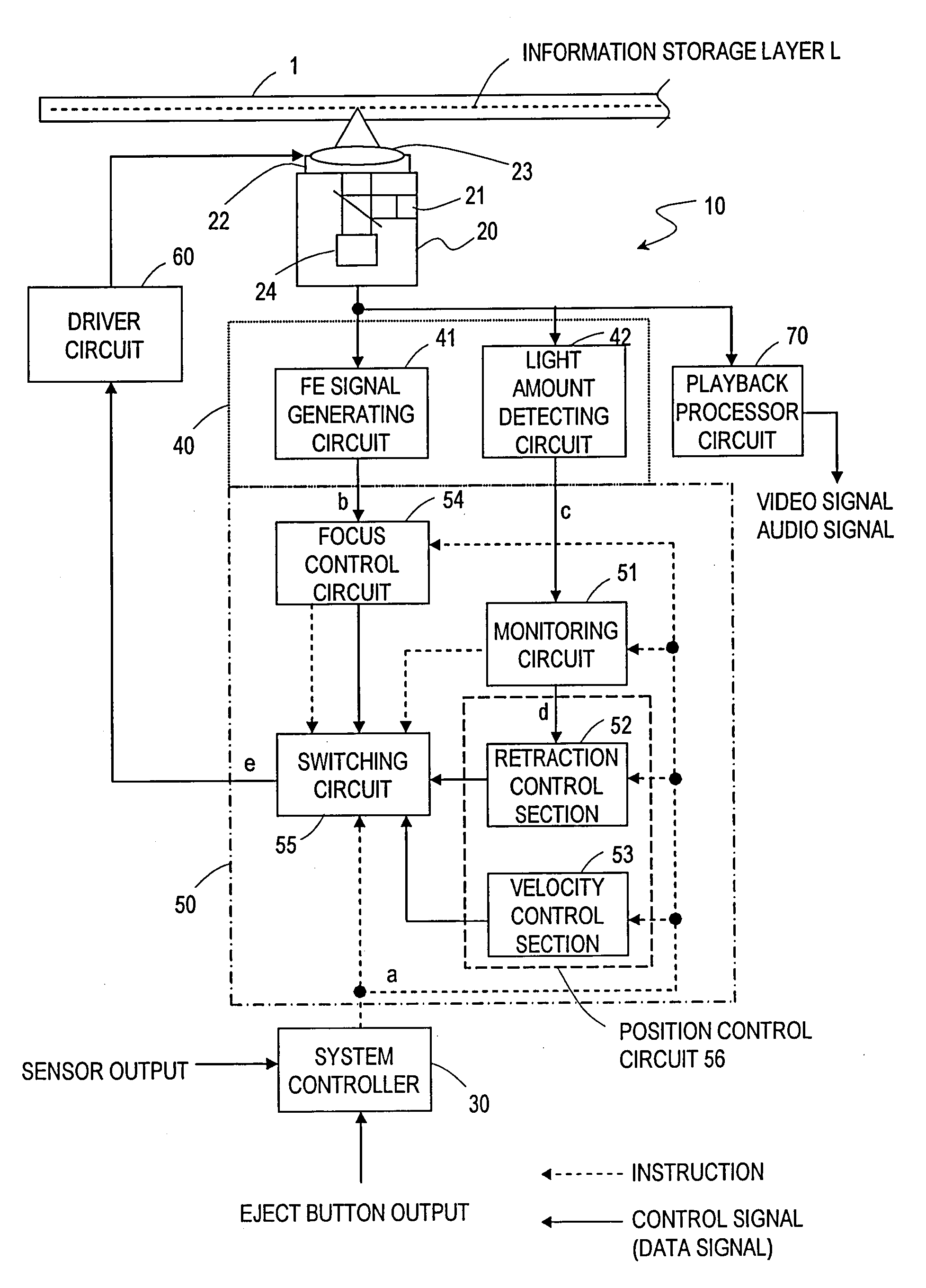
[0051] Hereinafter, preferred embodiments of an information processing apparatus according to the present invention will be described with reference to the accompanying drawings. In the following illustrative embodiments, the information processing apparatus is supposed to be a disk drive for reading data from a Blu-ray Disc (which will be simply referred to herein as a “disk 1”) and outputting a video signal, an audio signal and so on. The disk 1 is a disklike optical information storage medium that is insertable into, and removable from, the disk drive 10, and has a storage capacity of 25 gigabytes, for example. FIG. 3 shows an arrangement of functional blocks in a disk drive 10 according to a preferred embodiment of the present invention. The disk drive 10 includes an optical pickup 20, a system controller 30, a signal processor 40, a disk controller 50, a driver circuit 60 and a playback processor circuit 70.

[0052] The optical pickup 20 radiates a laser beam toward the informat...


PUM

PropertyMeasurementUnit
wavelengthaaaaaaaaaa

Abstract

To provide an apparatus that can prevent an objective lens from colliding against a member of a disk drive, can get disk loading/unloading operations done quickly and can establish a focus controlled state swiftly. An information processing apparatus includes: a converging section for converging light; a shifting section for shifting the focus of the light by moving the converging section perpendicularly to an information storage layer of a storage medium responsive to a drive signal; a position control section for generating a position control signal to move the converging section at variable velocities; a focus control section for generating a focus control signal based on a light amount signal representing reflected light such that the focus is located in a focus controllable range; a switching section for selectively outputting the position control or focus control signal; and a driving section for outputting a drive signal responsive to the output signal. The switching section outputs the position control signal to shift the focus to the focus controllable range and the focus control signal.

Description

TECHNICAL FIELD [0001] The present invention relates to a technique of controlling a device for reading and / or writing data from / on a storage medium such as an optical disk. BACKGROUND ART [0002] To read and / or write data from / on a disk such as a DVD by using light that has been emitted from a laser diode or any other light source, the operation of a disk drive needs to be controlled such that the point of convergence (i.e., the focal point) of the light is always located right on the information storage layer of the disk. This type of control is called a “focus control”. To realize the focus control, an objective lens in an optical pickup is arranged near the disk. [0003] However, since the objective lens is located close to the disk, the objective lens might contact with, or collide against, the disk loaded or a member of the disk drive while no focus control is being performed. [0004] Thus, a technique of avoiding such a collision is needed. For example, Patent Document No. 1 dis...

Claims


Application Information

Patent Timeline
Patent Type & Authority Applications(United States)
IPC IPC(8): G02B27/40G11B7/00G11B7/085G11B7/09G11B7/12
CPCG11B7/08511G11B7/121G11B7/0945G11B7/085G11B7/09G11B7/095G11B20/10
Inventor YOSHIKAWA, AKIRAWATANABE, KATSUYA
Owner PANASONIC CORP
Why Eureka
Try Eureka