Air exit guidance

a technology for exiting doors and air, applied in the direction of domestic heating details, space heating and ventilation details, heating types, etc., can solve the problems of many passengers' perception of unpleasantness and annoying

Active Publication Date: 2007-02-22
BE AEROSPACE SYST
View PDF3 Cites 5 Cited by
  • Summary
  • Abstract
  • Description
  • Claims
  • Application Information

AI Technical Summary

Benefits of technology

[0004] Against this background, it is the object of the present invention to create a simply constructed air

Problems solved by technology

Common ventilation nozzles, as are for example arranged at present in the personal service units of passenger aircraft and passenger buses, as

Method used


Image

  • Air exit guidance
  • Air exit guidance

Examples


Embodiment Construction

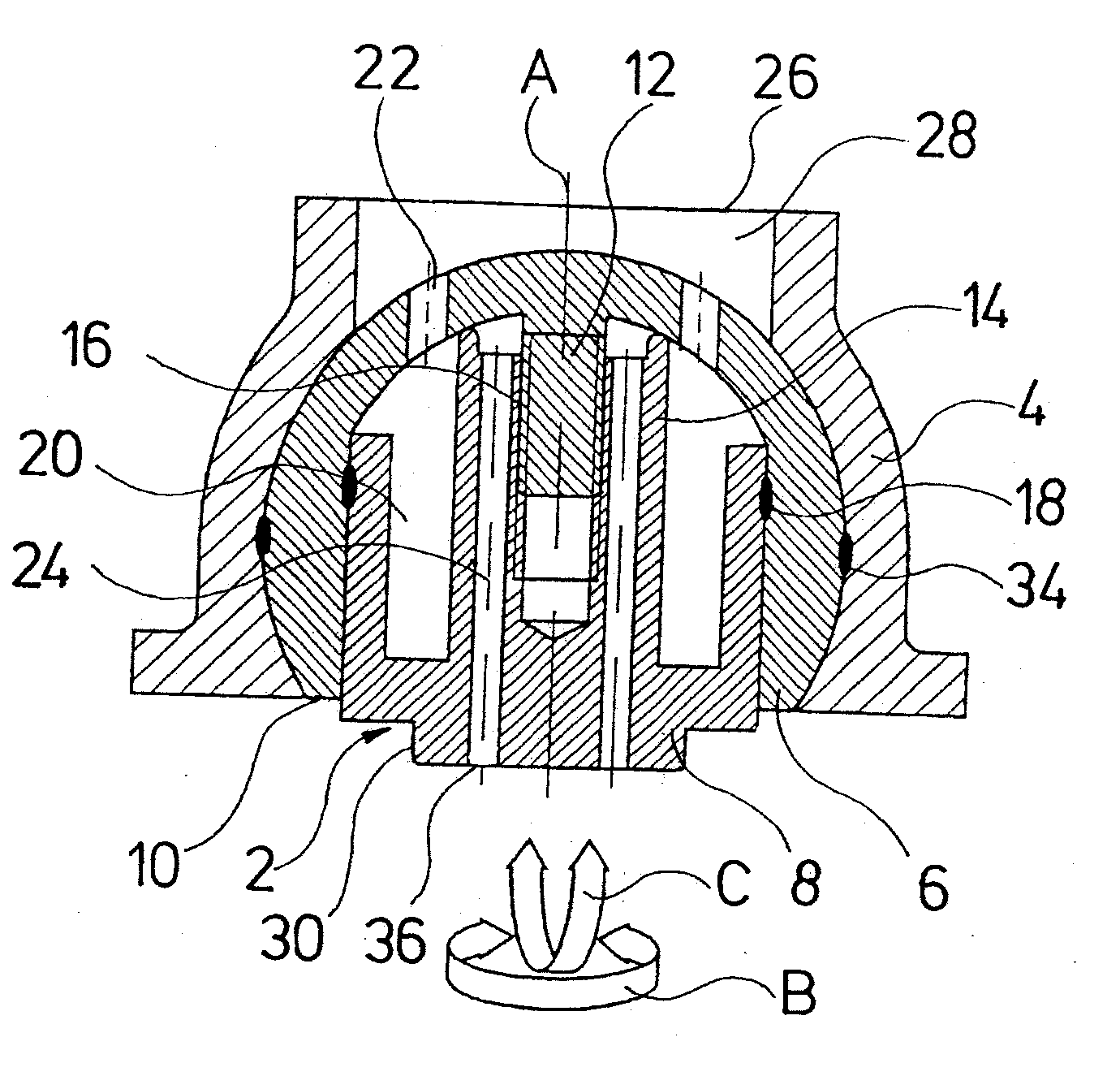
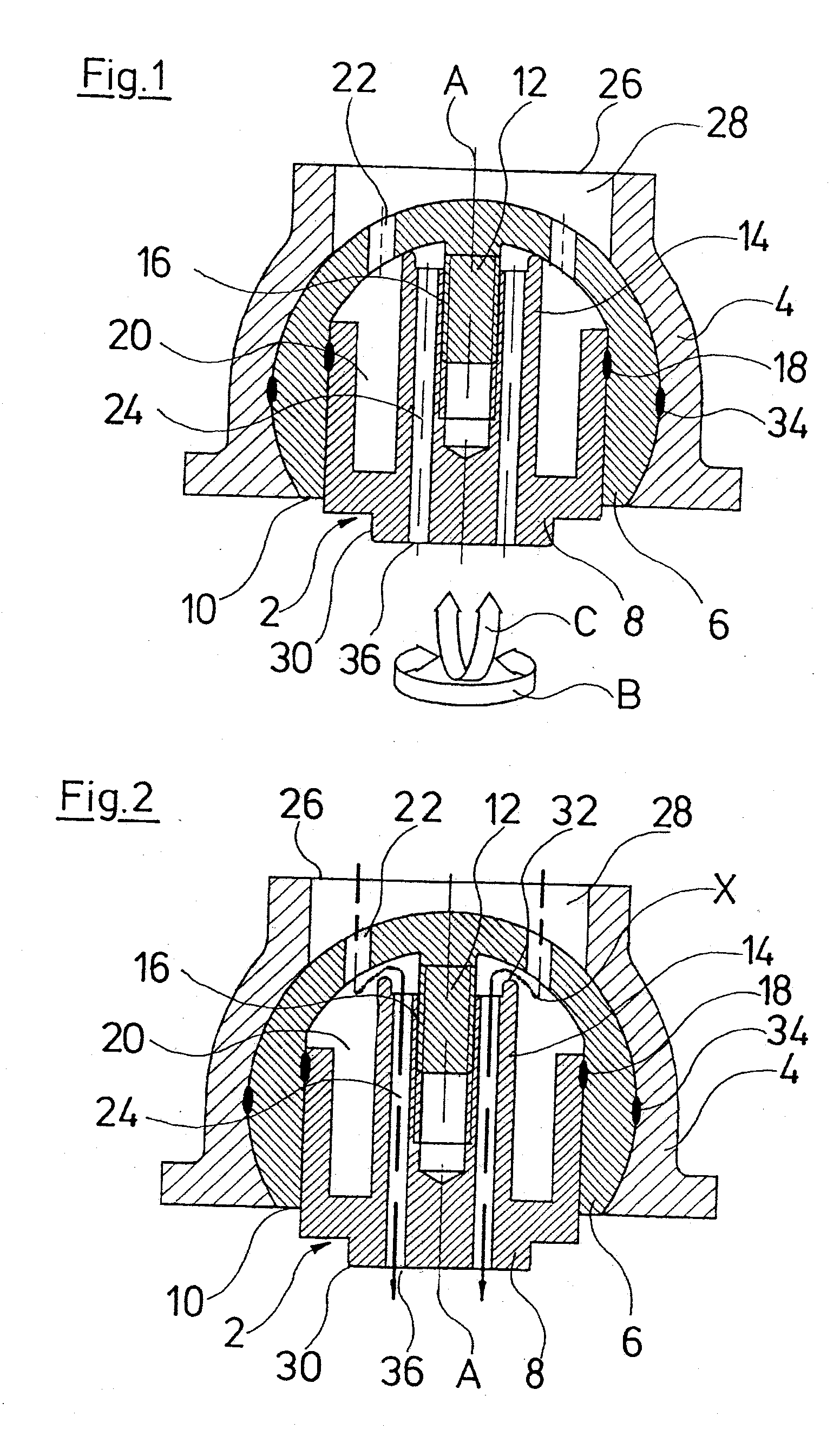
[0025] Referring to the drawings in particular, the air exit guidance system of the invention includes a flow guidance component 2 as well as a mounting and fastening part 4, in which the flow guidance component 2 is mounted. The flow guidance component 2 is formed in a two-part manner with a first component (ball part) 6 which receives a second component (actuator part) 8.

[0026] The first component 6 is designed in an essentially hollow manner and has an outer shape which corresponds to a ball with a cut-off spherical cap. The component 6 thus comprises a circular, open end-side 10. Proceeding from this end-side 10, the inner space of the component 6 is firstly designed in a cylindrical-hollow manner, in order then to run into a calotte-shaped, closed region. A threaded stem 12 extends on this calotte-shaped region of the inner space from the inner wall of the component 6 in the direction of the open end-side 10. Thereby, the threaded stem 12 has a longitudinal axis A which runs t...


PUM


Abstract

An air exit guidance which in particular is provided for arrangement in the personal service unit of an passenger aircraft. The guidance includes an air inlet and an air outlet as well as an adjustable throttle which is arranged at the inflow side of the air exit guidance.

Description

CROSS REFERENCE TO RELATED APPLICATIONS [0001] This application claims the benefit of priority under 35 U.S.C. §119 of German Patent Application DE 10 2005 039 236.9-16 filed Aug. 19, 2005, the entire contents of which are incorporated herein by reference. FIELD OF THE INVENTION [0002] The invention relates to an air exit guidance, in particular for the arrangement in the personal service unit of a passenger aircraft. BACKGROUND OF THE INVENTION [0003] Common ventilation nozzles, as are for example arranged at present in the personal service units of passenger aircraft and passenger buses, as well as the dashboards of motor vehicles, create flow noises during use, which are perceived by many passengers to be unpleasant and annoying. SUMMARY OF THE INVENTION [0004] Against this background, it is the object of the present invention to create a simply constructed air exit guidance which is uncomplicated in its manufacture and is improved with regard to the emission of noise. [0005] Acc...

Claims


Application Information

Patent Timeline
IPC IPC(8): B60H1/30
CPCB60H1/3442B64D13/00B64D2013/003
Inventor MECKES, RUDIGERRITTNER, WOLFGANG
Owner BE AEROSPACE SYST
Why Eureka
Try Eureka