Methanol synthesis and reaction system
- Summary
- Abstract
- Description
- Claims
- Application Information
AI Technical Summary
Benefits of technology
Problems solved by technology
Method used
Image
Examples
example 1
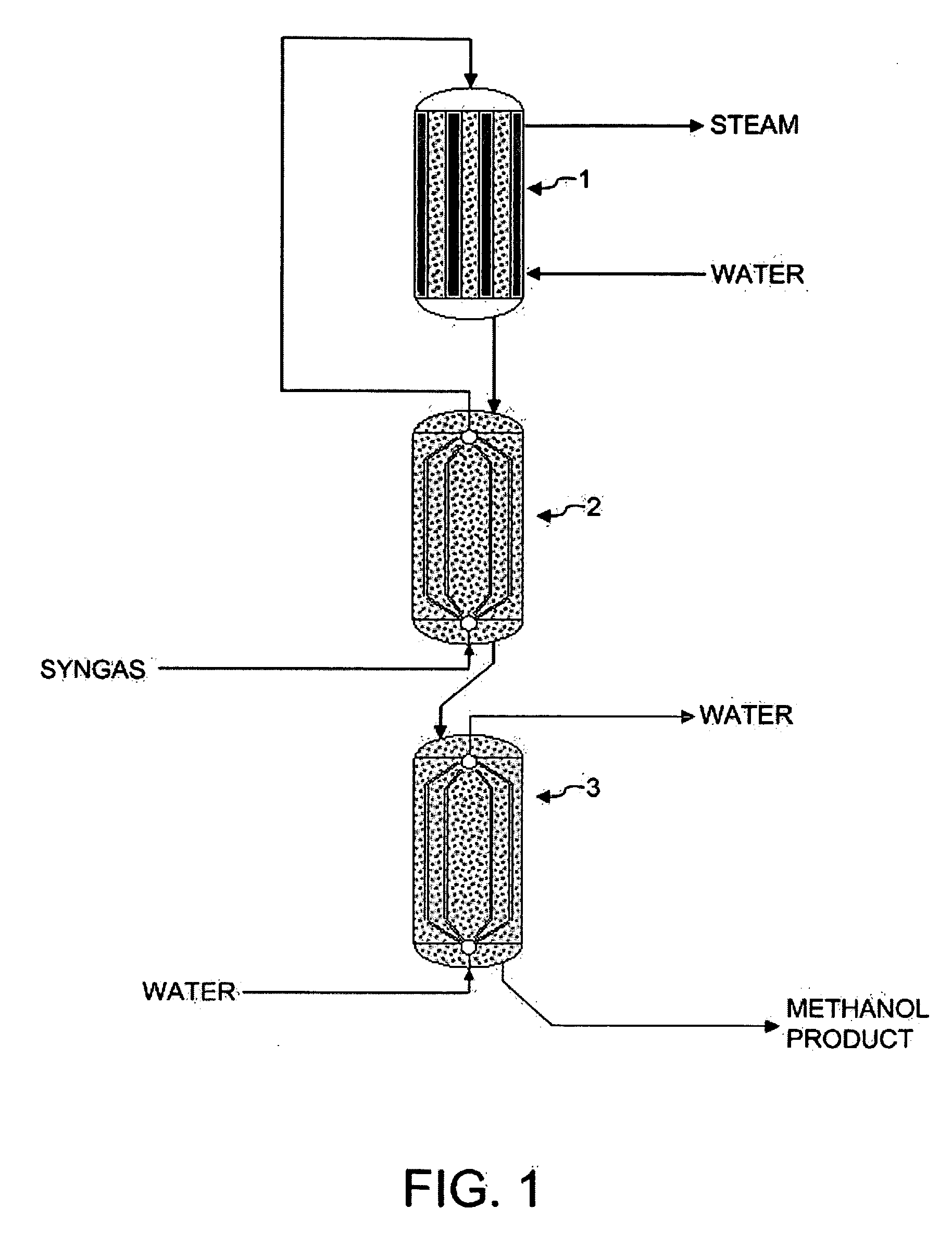
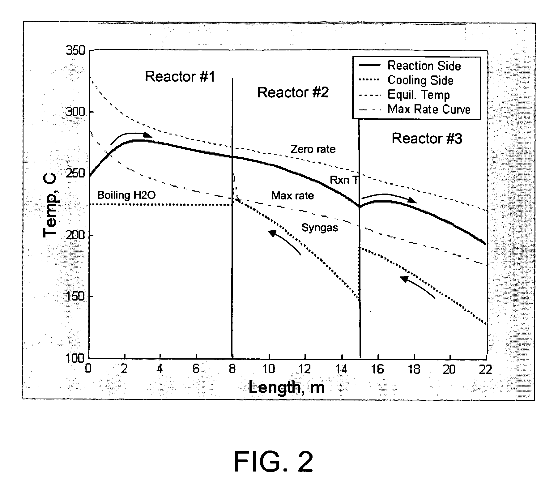
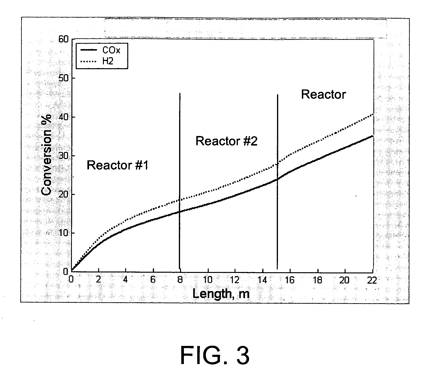
[0070] The reaction system of FIG. 1 was simulated using a reactor kinetic and heat transfer model, described in Example 4. Syngas feed was set at 147° C. (entering reactor 2, prior to preheating), methanol product from reactor 3 was at 192° C., and system pressure was at 47 bar, with a 1 bar pressure drop across the system. Reactor 1 inlet temperature was 247° C., and reactor 1 outlet temperature was 263° C. Reactor 1 was cooled using medium pressure boiling water at 225° C. Reactor 2 was cooled using the effluent gas from Reactor 1. Reactor 3 was cooled using liquid water as a cooling medium. Water was input to the reactor 3 at a temperature of 128° C. and emerged from the reactor 3 at a temperature of 190° C. Additional reactor data is shown in Table 1.
example 2
[0071] A comparative example utilizing a single reactor with the same overall catalyst volume as that of the system in Example 1 was run. Water at the same temperature as reactor 1 of Example 1 (225° C.) was utilized as a cooling medium, with the water evaporating during the cooling process to form steam. All other feed conditions were identical to those of Example 1. The detailed reactor design data and results are shown in Table 1. The overall CO and CO2 conversion in this example is 26.4%, much lower than that of Example 1. This can be attributed to the fact that the high level cooling medium at 225° C. results in a reactor effluent temperature that is higher than that of Example 1. The higher effluent temperature results in a reduced equilibrium conversion level.
example 3
[0072] A second comparative example utilizing a single reactor with the same overall catalyst volume as that of the system in Example 1 was run. This second comparative example was similar to that of Example 2, except that conversion is improved over that of Example 2 by using a lower temperature cooling medium. The reactor volume and other conditions were otherwise the same. The cooling in this example was also evaporative water cooling, with the water boiling at 168° C. Additional reactor design data and results are shown in Table 1.
[0073] The data in Table 1 show that the coolant temperature used in this example achieved the same reactor effluent temperature as that in Example 1 (192° C.). Thus, the equilibrium driving force at the reactor exit in this example is identical to that in Example 1. The overall conversion in this example is 33.2%, which is somewhat less than in Example 1. In addition, the fact that the heat of reaction is recovered by generating 168° C. steam instead...
PUM
| Property | Measurement | Unit |
|---|---|---|
| Temperature | aaaaa | aaaaa |
| Temperature | aaaaa | aaaaa |
| Temperature | aaaaa | aaaaa |
Abstract
Description
Claims
Application Information
 - R&D
- Intellectual Property
- Life Sciences
- Materials
- Tech Scout
- Unparalleled Data Quality
- Higher Quality Content
- 60% Fewer Hallucinations
Browse by: Latest US Patents, China's latest patents, Technical Efficacy Thesaurus, Application Domain, Technology Topic, Popular Technical Reports.
© 2025 PatSnap. All rights reserved.Legal|Privacy policy|Modern Slavery Act Transparency Statement|Sitemap|About US| Contact US: help@patsnap.com


