
Muffler for an exhaust system

a technology of exhaust system and muffler, which is applied in the direction of gas passages, machines/engines, gas chambers, etc., can solve the problems of increased manufacturing complexity, unwanted negative effect on the interior of the vehicle, and possible design space problems

Inactive Publication Date: 2007-03-01
EBERSPAECHER CLIMATE CONTROL SYST GMBH & CO KG
View PDF29 Cites 12 Cited by
  • Summary
  • Abstract
  • Description
  • Claims
  • Application Information

AI Technical Summary

Benefits of technology

[0002] In dual-flow exhaust systems, i.e., in exhaust systems having two exhaust lines with exhaust gas flowing through them in parallel, it is customary for a muffler to be provided at approximately half the distance between the internal combustion engine and the tailpipes opening into the environment, with the two exhaust lines being assigned jointly to the muffler, which is usually referred to as a central muffler. If the exhaust system together with the internal combustion engine is accommodated in a motor vehicle, the two exhaust lines may be installed in a type of tunnel along the undercarriage of the vehicle when the internal combustion engine is mounted in the front end, said tunnel optionally being open at the bottom. The dimensions of this tunnel must be selected so that a critical thermal load on the tunnel walls can be prevented. At the same time, an attempt is made to make the dimensions of the tunnel as small as possible to thereby minimize any negative effects in the interior of the vehicle. Design space problems may occur, for example, if the dual-flow exhaust system must be equipped with a muffler in the area of the tunnel.
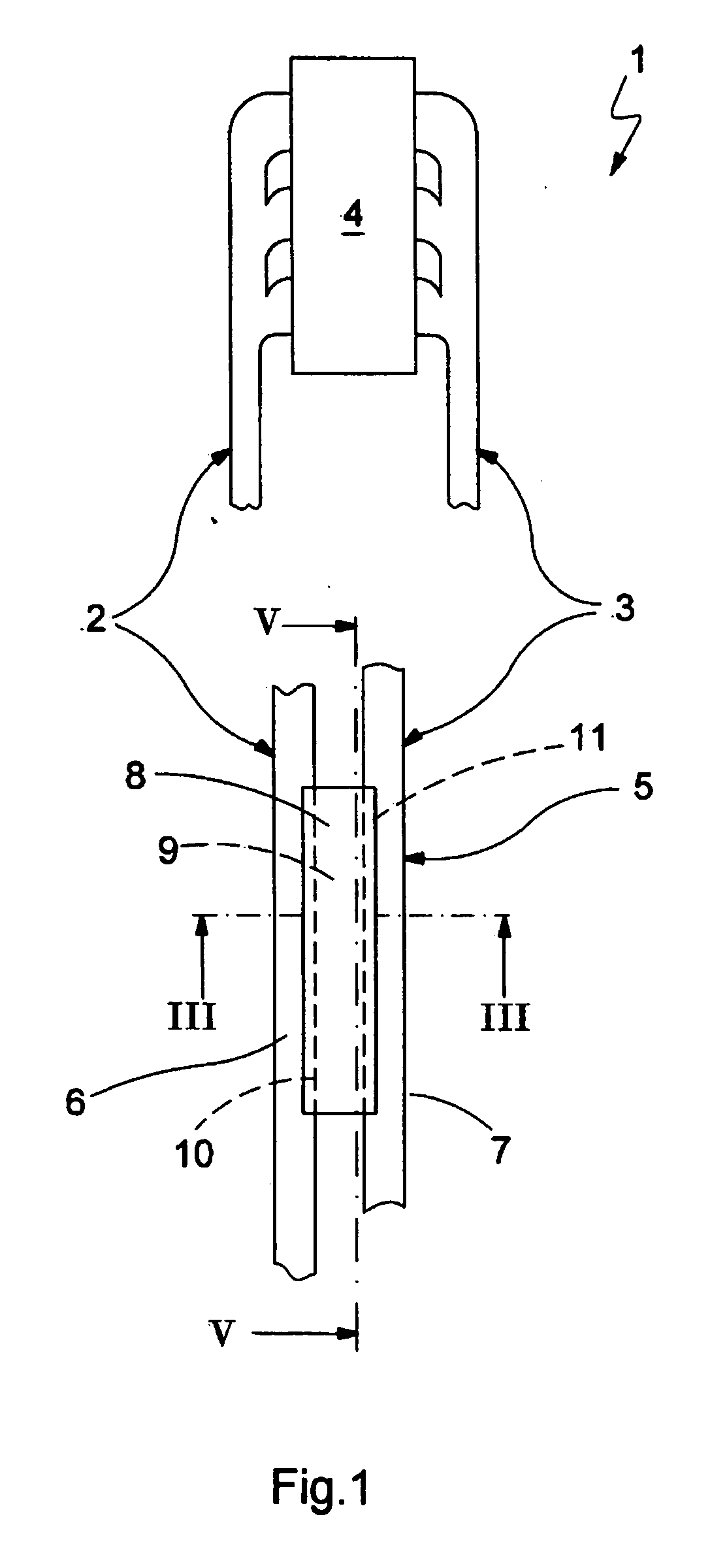
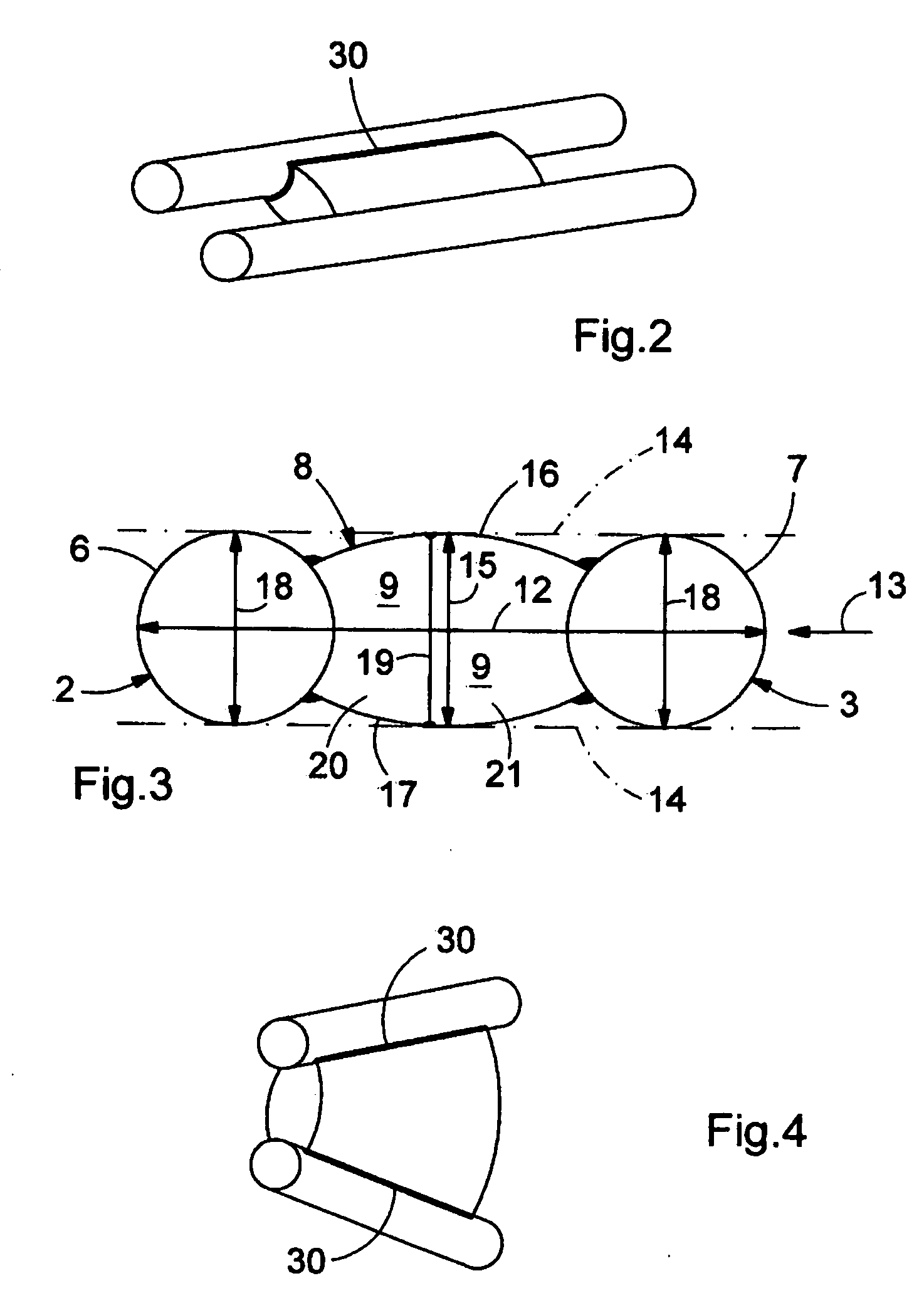
[0006] In an embodiment of the invention, the housing may be designed so that it is situated inside an outside contour of at least one of the pipes or protrudes maximally by 20% beyond this outside contour in a viewing direction oriented from one pipe to the other pipe. As a result of this design, the muffler needs only slightly more space or none at all across the longitudinal direction of the pipes, i.e., the exhaust lines and across the aforementioned viewing direction than do the pipes without the housing and / or the exhaust lines without the muffler. For installation of the exhaust system in a vehicle, this means that the tunnel need be enlarged only slightly in this direction or not at all.

Problems solved by technology

Design space problems may occur, for example, if the dual-flow exhaust system must be equipped with a muffler in the area of the tunnel.
Such a local increase in the size of the tunnel leads to unwanted negative effect on the interior of the vehicle and is also associated with an increased manufacturing complexity.

Method used


Image

  • Muffler for an exhaust system
  • Muffler for an exhaust system
  • Muffler for an exhaust system

Examples


Embodiment Construction

[0015] According to FIG. 1, an exhaust system 1 includes two exhaust lines 2, 3 with the help of which exhaust gas from an internal combustion engine 4 is emitted into an environment of the internal combustion engine 4 and / or a vehicle equipped therewith. Therefore, exhaust gas formed by the internal combustion engine 4 during operation can flow in parallel through the two exhaust lines 2, 3. According to this invention, a muffler 5 is connected jointly to the two exhaust lines 2, 3 and serves to influence the acoustics of the exhaust system 1. The muffler 5 has two pipes carrying the exhaust, namely a first pipe 6 and a second pipe 7.

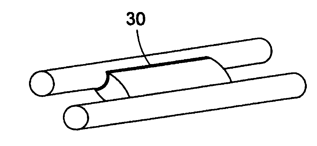
[0016]FIG. 1 shows an embodiment having an integral design. The muffler 5 is integrated into the exhaust system 1 in such a way that the first pipe 6 is formed by a longitudinal section of the first exhaust line 2, while the second pipe 7 is formed by a longitudinal section of the second exhaust line 3. In contrast with that, FIGS. 2 and 4 show two em...


PUM


Abstract

The present invention relates to a muffler for an exhaust system of an internal combustion engine having an exhaust gas-carrying first pipe which is connectable to a first exhaust line of the exhaust system or forms an integral component of the first exhaust line, and an exhaust gas-carrying second pipe which is connectable to a second exhaust line of the exhaust system or forms an integral component of the second exhaust line. To design the muffler to be as compact as possible, a housing of the muffler includes a damper space situated between the pipes and has two longitudinal side walls each formed by a wall section of one of the pipes that is permeable for airborne sound.

Description

FIELD OF THE INVENTION [0001] The present invention relates to a muffler for an exhaust system of an internal combustion engine. The invention also relates to an exhaust system equipped with such a muffler. BACKGROUND OF THE INVENTION [0002] In dual-flow exhaust systems, i.e., in exhaust systems having two exhaust lines with exhaust gas flowing through them in parallel, it is customary for a muffler to be provided at approximately half the distance between the internal combustion engine and the tailpipes opening into the environment, with the two exhaust lines being assigned jointly to the muffler, which is usually referred to as a central muffler. If the exhaust system together with the internal combustion engine is accommodated in a motor vehicle, the two exhaust lines may be installed in a type of tunnel along the undercarriage of the vehicle when the internal combustion engine is mounted in the front end, said tunnel optionally being open at the bottom. The dimensions of this tu...

Claims


Application Information

Patent Timeline
Patent Type & Authority Applications(United States)
IPC IPC(8): F01N1/02F01N13/04F01N13/18
CPCF01N1/003F01N1/24F01N13/1872F01N13/1894F01N2450/22F01N2470/02F01N2490/15
Inventor KRUEGER, JANHILDEBRAND, JOACHIMACKERMANN, DIETER
Owner EBERSPAECHER CLIMATE CONTROL SYST GMBH & CO KG
Learn More