
High resolution resistivity earth imager

a resistivity earth and imager technology, applied in the field of hydrocarbon exploration, can solve the problems of insufficient coverage, insufficient resistivity, sensitive contact devices, etc., and achieve the effect of accurate imaging of boreholes, high resolution and high resistivity

Active Publication Date: 2007-03-01
BAKER HUGHES INC
View PDF14 Cites 47 Cited by
  • Summary
  • Abstract
  • Description
  • Claims
  • Application Information

AI Technical Summary

Benefits of technology

[0013] Another embodiment of the invention is a computer readable medium for use with an apparatus used for evaluating an earth formation penetrated by a borehole. The apparatus includes at least one measure electrode connected to a source of electrical current and conveying a measure current into the formation at a plurality of frequencies. The medium includes instructions which enable a processor to estimate a resistivity parameter of the earth formation based at least in part on a real and imaginary part of an impedance determined at the plurality of frequencies. The instructions may further enable the processor to determine a standoff of the measure electrode. The medium may be a ROM, an EPROM, an EAROM, a Flash Memory, and / or an Optical disk.

Problems solved by technology

The Dory patent discloses the use of an acoustic sensor in combination with pad mounted electrodes, the use of the acoustic sensors making it possible to fill in the gaps in the image obtained by using pad mounted electrodes due to the fact that in large diameter boreholes, the pads will necessarily not provide a complete coverage of the borehole.
The prior art devices, being contact devices, are sensitive to the effects of borehole rugosity: the currents flowing from the electrodes depend upon good contact between the electrode and the borehole wall.
If the borehole wall is irregular, the contact and the current from the electrodes is irregular, resulting in inaccurate imaging of the borehole.
A second drawback is the relatively shallow depth of investigation caused by the use of measure electrodes at the same potential as the pad and the resulting divergence of the measure currents.
However, if the mud has a finite conductivity, the condition is hard to satisfy.

Method used


Image

  • High resolution resistivity earth imager
  • High resolution resistivity earth imager
  • High resolution resistivity earth imager

Examples


Embodiment Construction

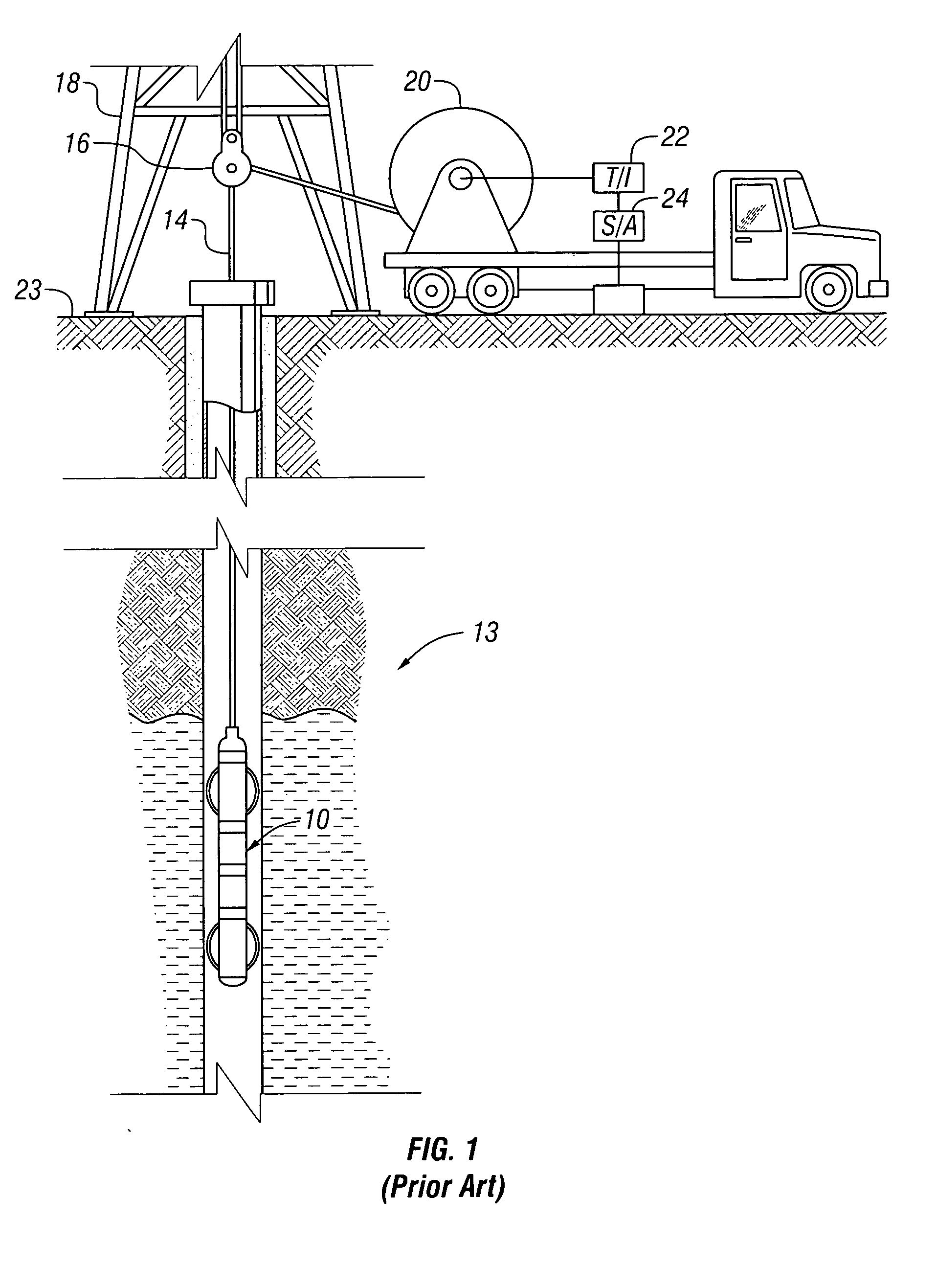
[0023]FIG. 1 shows an exemplary imaging tool 10 suspended in a borehole 12, that penetrates earth formations such as 13, from a suitable cable 14 that passes over a sheave 16 mounted on drilling rig 18. By industry standard, the cable 14 includes a stress member and seven conductors for transmitting commands to the tool and for receiving data back from the tool as well as power for the tool. The tool 10 is raised and lowered by draw works 20. Electronic module 22, on the surface 23, transmits the required operating commands downhole and in return, receives data back which may be recorded on an archival storage medium of any desired type for concurrent or later processing. The data may be transmitted in analog or digital form. Data processors such as a suitable computer 24, may be provided for performing data analysis in the field in real time or the recorded data may be sent to a processing center or both for post processing of the data.

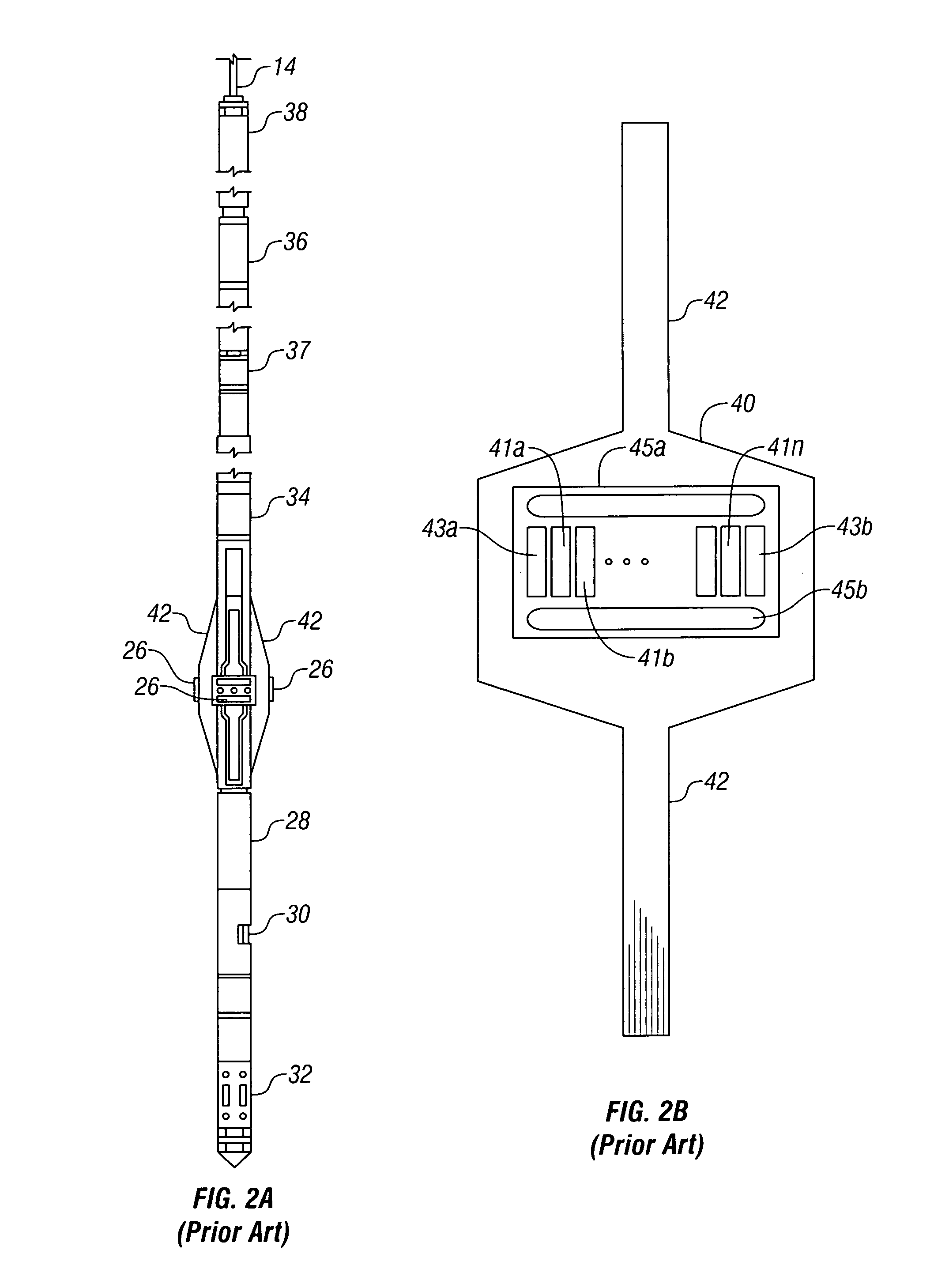
[0024]FIG. 2a is a schematic external view of...


PUM


Abstract

Phase-sensitive measurements are made by a resistivity imaging tool in a borehole having non-conductive mud in a conductive earth formation at a plurality of frequencies. From the phase sensitive measurements, the formation resistivity can be determined with higher sensitivity than is possible with the single frequency measurements. Tool standoff can also be determined from a knowledge of the mud resistivity and / or dielectric constant. Formation resistivity may also be determined when the effect of formation capacitance cannot be ignored.

Description

BACKGROUND OF THE INVENTION [0001] 1. Field of the Invention [0002] This invention generally relates to exploration for hydrocarbons involving electrical investigations of a borehole penetrating an earth formation. More specifically, this invention relates to highly localized borehole investigations multifrequency focusing of survey currents injected into the wall of a borehole by capacitive coupling of electrodes on a tool moved along the borehole with the earth formation. [0003] 2. Background of the Art [0004] Electrical earth borehole logging is well known and various devices and various techniques have been described for this purpose. Broadly speaking, there are two categories of devices used in electrical logging devices. In the first category, a measure electrode (current source or sink) are used in conjunction with a diffuse return electrode (such as the tool body). A measure current flows in a circuit that connects a current source to the measure electrode, through the earth...

Claims


Application Information

Patent Timeline
IPC IPC(8): G01V3/02G01V3/04G01V3/06
CPCG01V3/24
Inventor BESPALOV, ALEXANDRE N.ITSKOVICH, GREGORY B.
Owner BAKER HUGHES INC
Learn More