Video image processing with remote diagnosis and programmable scripting

a video image and remote diagnosis technology, applied in the field of digital video, can solve problems such as error magnification, reduced image quality and processing efficiency, and increased redundancy and cos

Active Publication Date: 2007-03-01
NVIDIA CORP
View PDF42 Cites 46 Cited by
  • Summary
  • Abstract
  • Description
  • Claims
  • Application Information

AI Technical Summary

Problems solved by technology

This results not only in increased redundancy and cost, it also potentially results in reduced image quality and processing efficiency.
For similar reasons, error magnification may occur, such as where processing by the second stage is not well-tuned to processing by the first stage.
A further drawback is the sequential flow through the stages such that additional, targeted processing can not be performed.
Sub-par image quality, high cost, and processing inefficiencies are problems that are faced in many digital video applications, including high definition television (HDTV).
Still further, architectures in prior systems can result in large, multiple silicon implementations that increase cost and / or produce functional redundancies.
Diagnosing, debugging, or fixing problems of current systems is typically difficult and expensive.
In such a setting, analysis of the pixels coming out of the image interpolation process may reveal image quality issues that are best handled by adjusting the de-interlacing processing parameters.
Meshing may be undesirable for moving pixels because meshing can create a “tearing” or “feathering” effect, due to the temporal shifts occurring between successive interlaced video frames.
As previously discussed, interpolative de-interlacing methods can cause blurring effects or other loss of sharpness.
While this potentially increases spatial resolution, it can result in motion artifacts (e.g., “mouse's teeth,” or “field tearing”) for those pixels representing moving objects.
Such replication of functionality will at times be undesirable.
For example, multiple motion estimation blocks can provide an inconsistent view of motion occurring within the video data, as it is likely that each block will employ a different motion assessment methodology.
The redundant functionality also will result in larger circuits and greater use of silicon, which in turn can lead to higher manufacturing costs.
A variety of other inefficiencies may result from such redundant functionality.
If not, then that stage's processing is prematurely suspended or terminated.
In this manner, group processing is performed according to FIG. 19C until all groups have been processed, however, some lower tier groups may not be processed, for example, if their processing time has been donated to higher tier groups such that no processing time remains for processing the lower tier groups.
For example, if the tag data indicates that a frame (or a group or groups of pixels) has a relatively flat field or solid color, then relatively less time is allocated for performing motion estimation on that frame (or group or group of pixels), because it is relatively difficult to obtain an accurate motion vector in such a situation (e.g., where there is less spatial detail from which to obtain the motion vector information).
Further, a pipeline segment may not use the tag data in the processing task.
Explaining the displayed image artifact to the vendor technical support engineer, however, will likely be difficult.
It is difficult to verbally describe a visual image artifact, the context of which may be peculiar to the particular image being displayed.
Moreover, there may be a language barrier that further complicates communication between the customer and the vendor technical support engineer.
Still further, this approach doesn't give the technical support engineer any underlying state or other information about the video signal processing system or the image being processed or displayed.
This makes diagnosing or debugging a problem a difficult task for the technical support engineer, and sometimes results in the technical support engineer having to travel to the customer's location to perform on-site diagnosis or debugging, which increases delay, expense, or both.
In this way, the U.S. vendor's technical support engineer can also see the exact same anomaly being viewed as problematic by the customer.

Method used


Image

  • Video image processing with remote diagnosis and programmable scripting
  • Video image processing with remote diagnosis and programmable scripting
  • Video image processing with remote diagnosis and programmable scripting

Examples


example 1

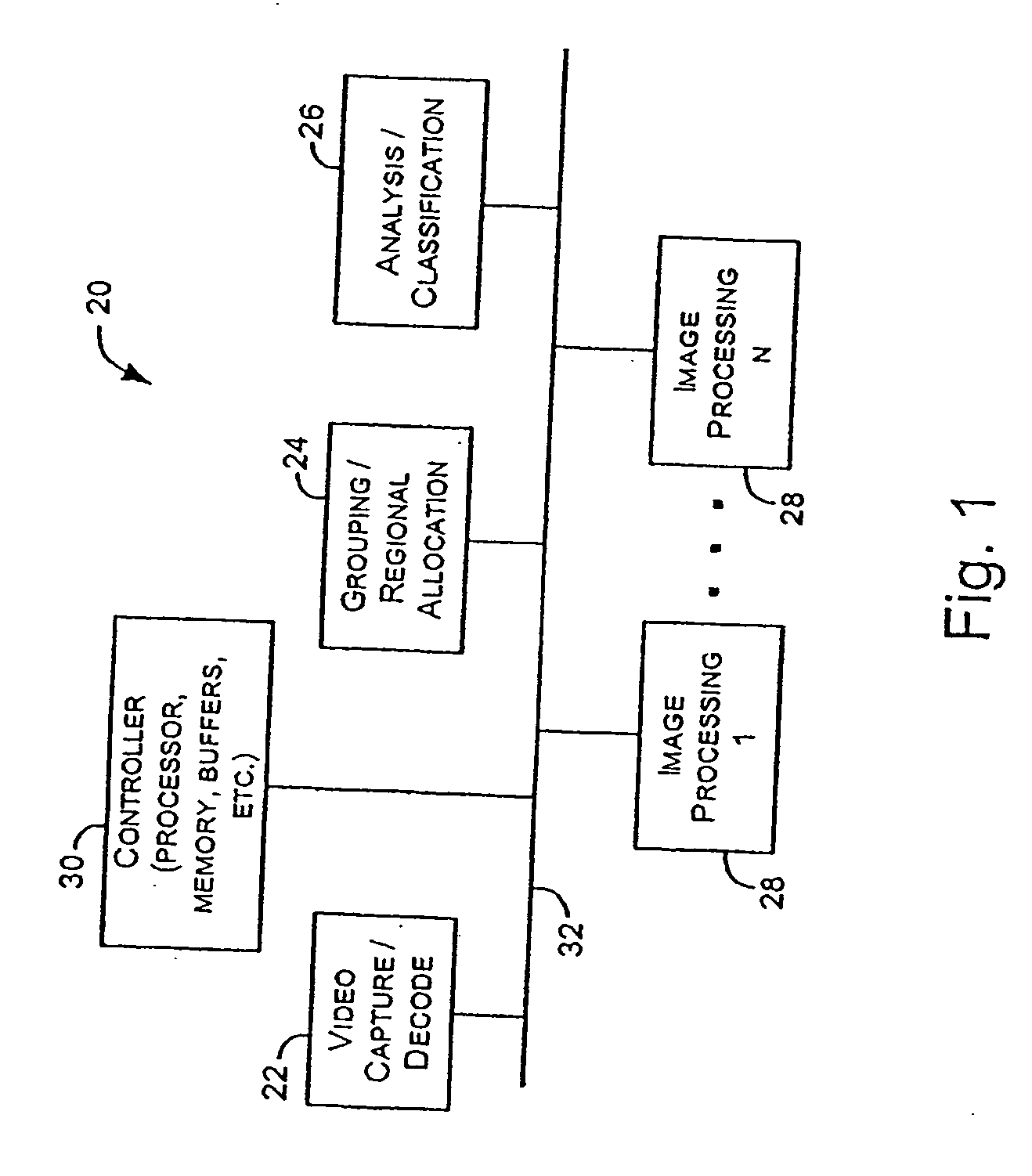
[0041]FIG. 1 schematically depicts an example of an image processing system 20. The image processing system 20 may include a block 22 for receiving and performing initial processing on an input video signal. The block 22 may be configured to handle analog and / or digital inputs. In the case of analog video, the block 22 may include subcomponents to capture and / or decode an analog video signal, so as to produce corresponding pixels representing the input video frame(s). For example, an analog video decoder including a suitable analog to digital converter (ADC) may be employed to produce pixels representing the input video frame. These pixels may then be clocked into or otherwise applied to the processing pipeline. In typical examples, the pixels are serially clocked into the system. In an example, the system 20 is fabricated within a single contiguous piece of silicon.

[0042] For analog video, a device such as the Philips 7119 may be used to provide the pixels to be captured by the pr...

example 2

[0080]FIG. 9 is a block diagram of one example of a conceptualization of portions of a system 900 for processing a digital video signal, such as for viewing on a high-definition television (HDTV) or like display 902. In this example, the system 900 includes a signal preprocessor 904. The signal preprocessor 904 receives and preprocesses one or more input signals, such as a digital video signal from a digital videocamera or a digital video signal of a digital television broadcast. An output of the signal preprocessor 904 is coupled to an input of a memory 906. The video pixel data and accompanying audio data of the resulting preprocessed signal is typically provided to and stored in a respective designated portion of the memory 906. Image analysis or processing stages 908A-N are also coupled to the memory 906. The pixel data stored in the memory 906 undergoes image analysis or processing by one or more of the stages 908A-N. An accompanying stage controller 910A-N is respectively coup...

example 3

[0114]FIG. 17 is a block diagram illustrating generally one example of portions of the memory 906 in more detail. In this example, the memory 906 includes a first-in-first-out frame buffer 1700 that receives a programmable number of frames 1702A-N of pixel data from the signal preprocessor 904. During the time when the pixel data frames 1702A-N are stored in the frame buffer, they are accessed and processed by the image analysis or processing stages 908, which typically results in the pixel data being altered (perhaps multiple times) before it is output by the frame buffer 1700 to the DTV display 902. In an illustrative example, the frame buffer 1700 includes about 30 to 40 frames of pixel data, which is stored in about 128 Mbytes of dynamic random access memory (DRAM). However, in another example, the frame buffer 1700 can be programmed to store a different number of frames of pixel data, or to use a different amount or type of memory.

[0115]FIG. 17 also illustrates tag data being ...


PUM


Abstract

This document discusses, among other things, systems and methods for receiving a local input video signal, processing the video signal, and providing a processed video signal to a local digital television display panel. A communications port includes an Ethernet or other communications network connector for allowing access to the video signal processing system by a remote device. This allows a remote user to remotely diagnose, debug, and even modify operation of the video signal processing system. In certain examples, this involves downloading a Lua script that can take partial or complete control over operation of the video signal processing system from resident instruction code. In certain examples, the video signal processing system includes pipelined image analysis or processing stages. Video signal data intermediate to such processing, or the processed video signal being provided to the local display can be communicated to the remote user.

Description

TECHNICAL FIELD [0001] This patent document pertains generally to digital video, and more particularly, but not by way of limitation, to digital video image processing systems and methods. BACKGROUND [0002] Existing systems and methods for processing digital video typically use separate and independent, fixed image processing blocks, such as for performing fixed de-interlacing, scaling, and other image processing functions. This results not only in increased redundancy and cost, it also potentially results in reduced image quality and processing efficiency. For example, where only pixel data is passed between the stages, processing enhancements achieved by a first stage may be counteracted by later processing by a second stage. For similar reasons, error magnification may occur, such as where processing by the second stage is not well-tuned to processing by the first stage. A further drawback is the sequential flow through the stages such that additional, targeted processing can not...

Claims


Application Information

Patent Timeline
Patent Type & Authority Applications(United States)
IPC IPC(8): H04N17/00H04N3/27H04N5/14
CPCH04N19/176H04N19/172H04N19/46H04N19/42H04N19/137H04N19/154H04N19/117
Inventor MEAD, JOHNRUGGIERO, CARL J.MOXON, THOMAS
Owner NVIDIA CORP
Why Eureka
Try Eureka