Dynamic amplitude and spectral shaper in fiber laser amplification system

a fiber laser and amplitude technology, applied in the direction of laser details, wave amplification devices, electrical equipment, etc., can solve the problems of limited cpa systems, limited cpa systems, and difficulties of ordinary skill in the art, and achieve the effects of improving the accuracy of cpa systems

Inactive Publication Date: 2007-03-01
POLARONYX
View PDF8 Cites 32 Cited by
  • Summary
  • Abstract
  • Description
  • Claims
  • Application Information

AI Technical Summary

Benefits of technology

[0008] It is a further aspect of this invention that the acoustic optic dispersive shaper (AODS) as a dispersive component can be an active and programmable dispersive component to interactively generate adjustable levels of dis...

Problems solved by technology

Even though current technologies of fiber laser have made significant progress toward achieving a compact and reliable fiber laser system providing high quality output laser with ever increasing output energy, however those of ordinary skill in the art are still confronted with technical limitations and difficulties.
Specifically, in a fiber laser system implemented with the Chirped Pulse Amplification (CPA) for short pulse high power laser amplifier, the CPA systems are still limited by the technical difficulties that the third order dispersion (TOD) limits the scalability of the laser systems.
Such limitations were not addressed in the conventional technologies due to the fact that the conventional solid-state laser utilizes Grating-Lens combination and Treacy compressor for pulse stretching and compressing.
Ideally, in such solid-state systems, all orders of dispersion can be compensated, but the material dispersion can distor...

Method used


Image

  • Dynamic amplitude and spectral shaper in fiber laser amplification system
  • Dynamic amplitude and spectral shaper in fiber laser amplification system
  • Dynamic amplitude and spectral shaper in fiber laser amplification system

Examples


Embodiment Construction

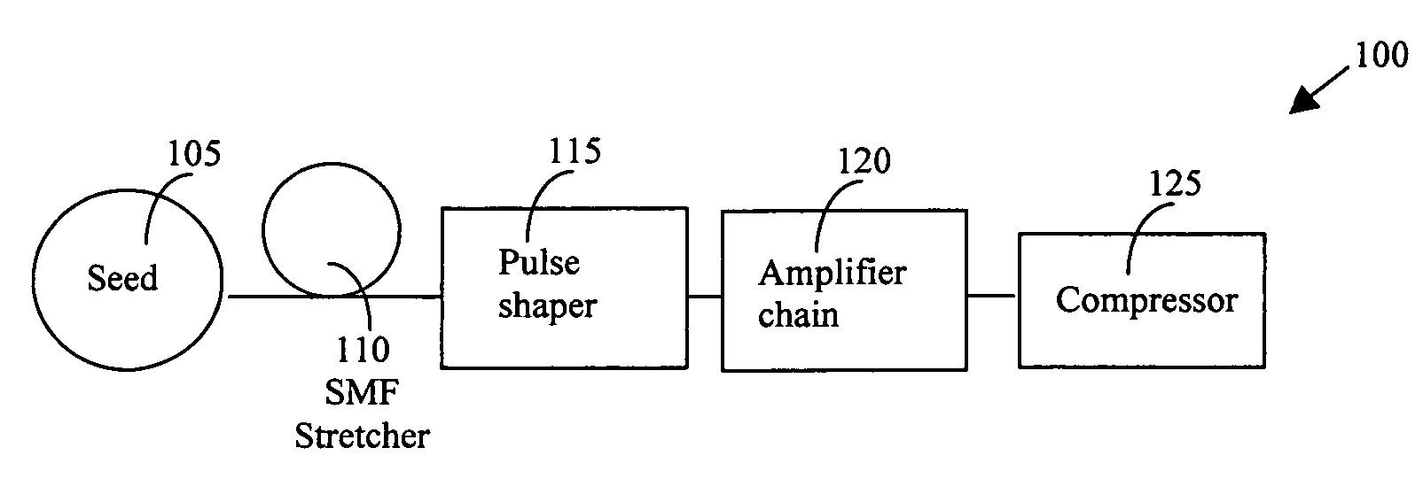
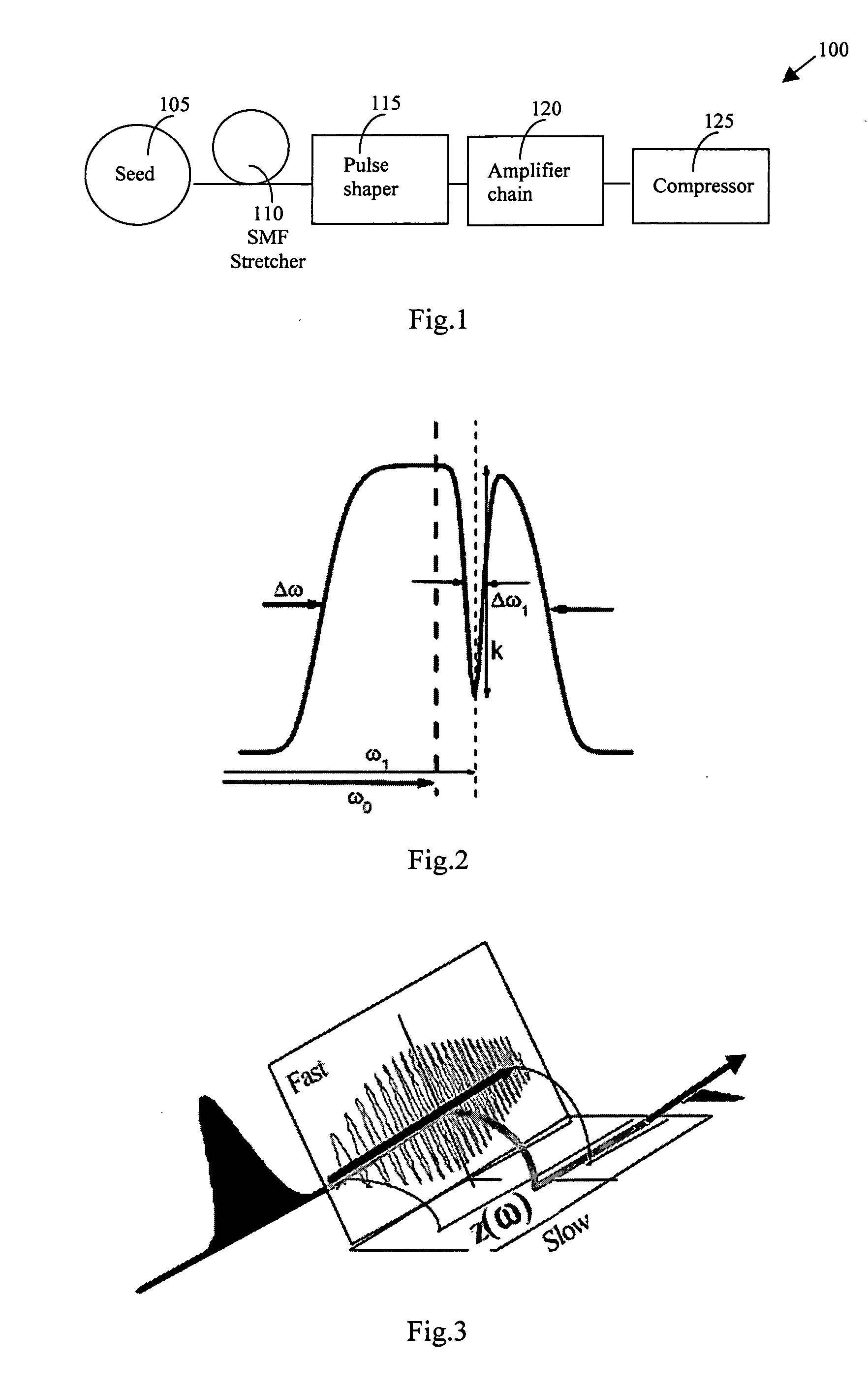
[0017] Referring to FIG. 1 for a schematic diagram of a fiber laser system 100 of this invention that implements a dispersion compensator of this invention. The laser system 100 includes a laser seed 105 for generating a seed laser for projecting into a laser stretcher 110 comprises single mode fiber (SMF) to stretch the laser pulse. The stretcher 110 generates laser pulse with stretched pulse width is projected into a pulse shaper 115. The pulse shaper 115 applies an amplitude-and-spectral modulation as will be described below to shape the laser pulses for projecting into a series of laser amplifiers 120 to amplify the laser into higher energy. The amplified laser is then projected into a compressor 125 to recompress the pulse width of the laser to output a laser with the original pulse width.

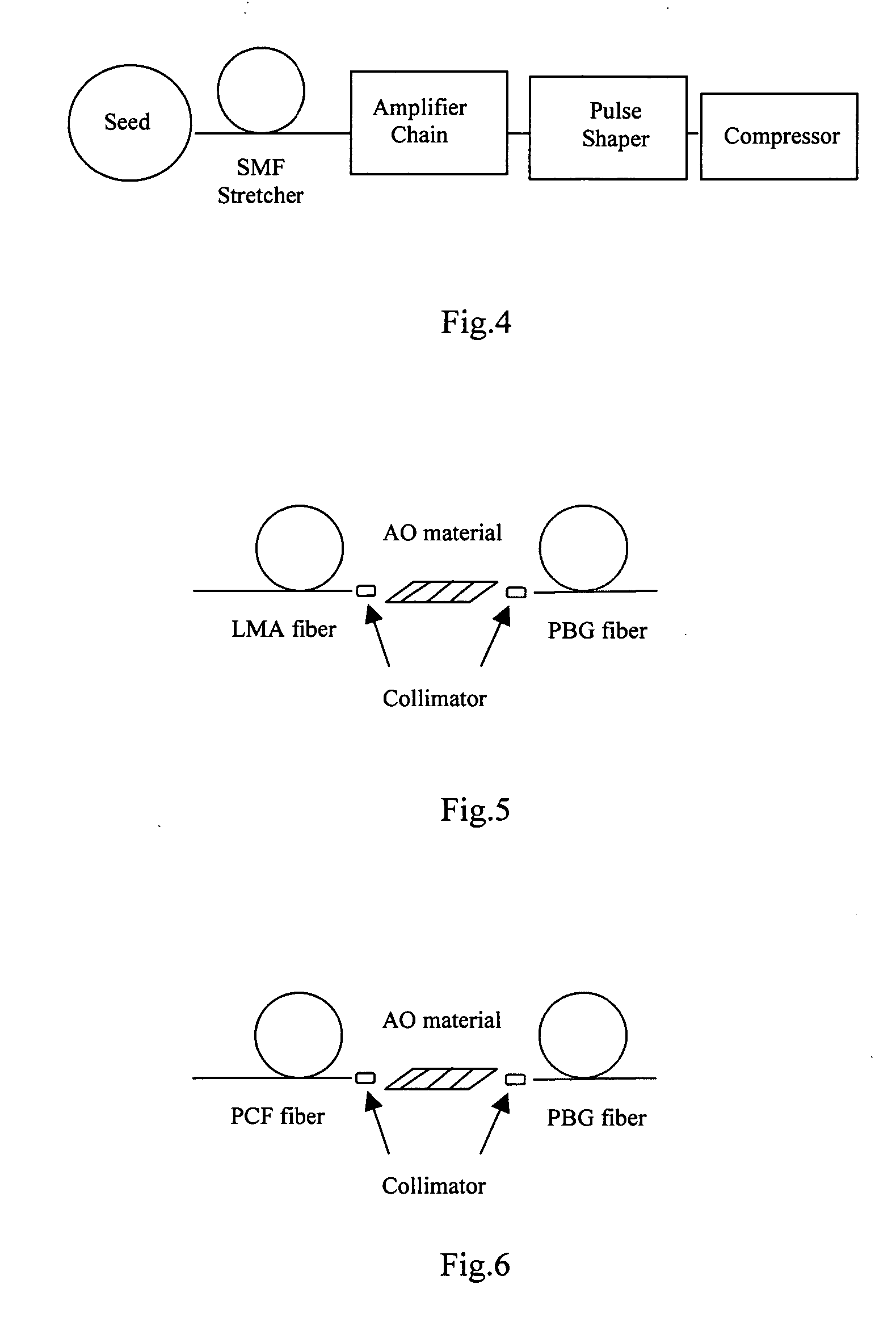
[0018] The pulse shaper 115 implements an acoustic-optic dispersive shaper (AODS) as a dispersive component. In its working range, the AODS can arbitrarily modulate both the spectrum shape an...


PUM


Abstract

A method for overcoming the drawback in a fiber CPA laser system that includes a process of generating a large negative TOD by implementing an AODS in a pulse shaper as a dispersive component. The AODS is implemented to arbitrarily modulate both the spectrum shape and phase to control with controllable amplitude to generate different orders of dispersions including a large negative TOD for compensating the positive TOD generated by the pulse stretching and amplification processes. The AODS, implemented as a dispersive component, can be an active and controllable dispersive component to generate adjustable levels of dispersions for flexibly compensating any order of dispersions generated in the amplifier chain including the nonlinear phase shift. The AODS implemented as a dispersive component can be an active and programmable dispersive component to interactively generate adjustable levels of dispersions in response to output laser amplitude and pulse shape measurements for flexibly compensating any order of dispersions generated in the amplifier chain including the nonlinear phase shift to achieve the shortest pulse duration.

Description

[0001] This Formal Application claims a Priority Date of Aug. 29, 2005 benefited from a Provisional Patent Applications 60 / 713,650, 60 / 713,653, and 60 / 713,654 and a Priority Date of Sep. 1, 2005 benefited from Provisional Application 60 / 714,468 and 60 / 714,570 filed by one of the same Applicants of this application.FIELD OF THE INVENTION [0002] The present invention relates generally to apparatuses and methods for providing fiber laser system. More particularly, this invention relates a design for dispersion compensation in Chirped Pulse Amplification (CPA) fiber laser system by dynamically shaping the amplitude and spectrum. BACKGROUND OF THE INVENTION [0003] Even though current technologies of fiber laser have made significant progress toward achieving a compact and reliable fiber laser system providing high quality output laser with ever increasing output energy, however those of ordinary skill in the art are still confronted with technical limitations and difficulties. Specifical...

Claims


Application Information

Patent Timeline
IPC IPC(8): H04B10/12
CPCH04B10/299H01S3/0057
Inventor LIU, JIANXIA, JIANGFAN
Owner POLARONYX
Why Eureka
Try Eureka