Warming apparatus with heater produced by pcb
- Summary
- Abstract
- Description
- Claims
- Application Information
AI Technical Summary
Benefits of technology
Problems solved by technology
Method used
Image
Examples
example 1
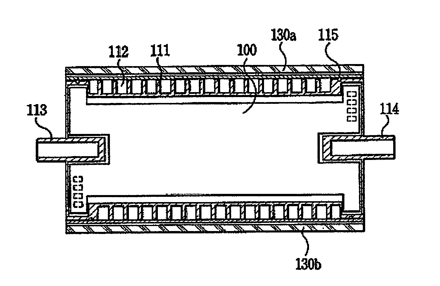
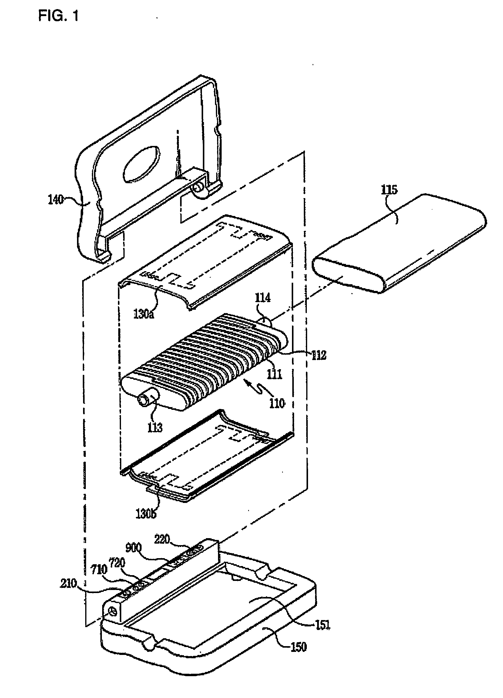
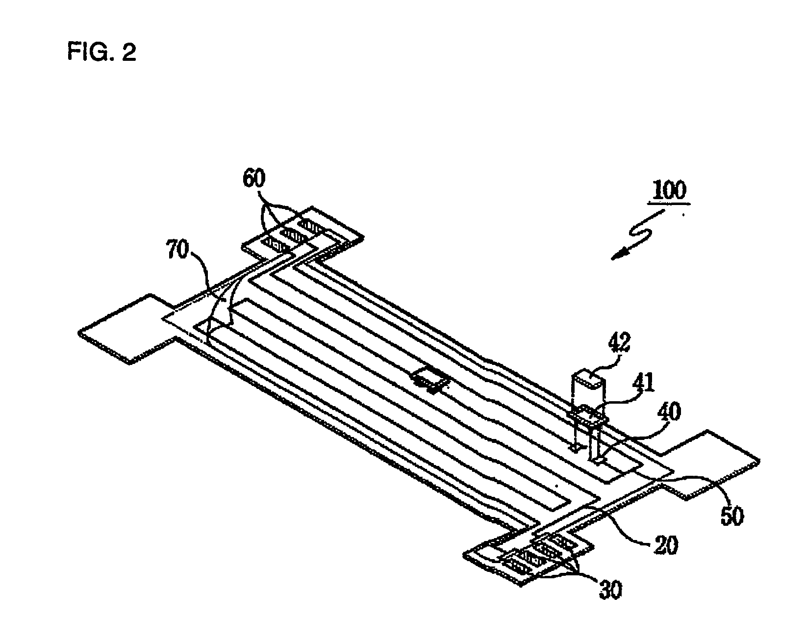
[0032]FIG. 1 shows a separate prospective view illustrating a heating apparatus having a PCT-type heater in accordance with the present invention. As shown in FIG. 1, the heating apparatus comprises a body 110 including a first connecting portion 113 having a tube which is connected to the first connection portion 113 and receives a fluid supplied from an instillation room, a path 112 having the shape of a spiral screw thread to allow the fluid to flow and a second connecting portion 114 for supplying the fluid flowing through the path 112 to an injection syringe; an inner cover 115 inserted into the body 110 and fixedly attached thereto in a ultrasonic, high-frequency, or adhesive manner for preventing the fluid from flowing out; middle covers 130a, 130b for closely fixing the body 110 and the inner cover 115 against each other; a PCB-type heater 100 inserted into the inside of the top surface 130a and bottom surface 130b of the middle cover for heating the fluid flowing through th...
example 2
[0046]FIG. 8 is a cross-sectional view of another embodiment of the heating apparatus shown in FIG. 1.
[0047] Referring to FIG. 8, the heating apparatus includes a body 110, which includes a first connecting portion 113 having a tube which receives a fluid supplied from an instillation room, a path 112 having the shape of a spiral screw thread to enable the fluid to flow and a second connecting portion for supplying the fluid flowing through the path to an injection syringe, an inner cover 115 inserted into the body 110 and fixedly attached thereto in an ultrasonic mode or a high frequency mode or using adhesive for preventing the fluid from flowing out, middle covers 130a, 130b for closely fixing the body 110 and the inner cover 115 against each other, and a PCB-type heater 100 inserted into the inside of the body 110, for heating the fluid flowing through the path 112 so that the fluid is maintained at a prescribed temperature.
[0048] Though not shown in the drawing, in the same m...
example 3
[0050]FIG. 9 is a cross-sectional view of another embodiment of the heating apparatus shown in FIG. 1.
[0051] Referring to FIG. 9, the heating apparatus includes a body 110a, which includes a first connecting portion 113 having a tube which is connected to the first connection portion and receives a fluid supplied from an instillation room, a path 112a having the shape of a zigzag to enable the fluid to flow, and a second connecting portion 114 for supplying the fluid flowing through the path 112a to an injection syringe, a middle cover 130c adhered to a surface where the path 112a is formed in an ultrasonic, a high frequency or adhesive manner, for preventing the fluid from flowing out, and a PCB-type heater 100 inserted into at least one inside of the inside of the body 112a and the inside of the middle cover 130c for heating the fluid flowing through the path 112a so that the fluid is maintained at a prescribed temperature.
[0052] In this time, the path 112a is formed by a projec...
PUM
 Abstract
Description
Claims
Application Information
 - R&D
- Intellectual Property
- Life Sciences
- Materials
- Tech Scout
- Unparalleled Data Quality
- Higher Quality Content
- 60% Fewer Hallucinations
Browse by: Latest US Patents, China's latest patents, Technical Efficacy Thesaurus, Application Domain, Technology Topic, Popular Technical Reports.
© 2025 PatSnap. All rights reserved.Legal|Privacy policy|Modern Slavery Act Transparency Statement|Sitemap|About US| Contact US: help@patsnap.com


