Prosthetic intervertebral discs

a technology of intervertebral discs and prostheses, which is applied in the field of prosthetic intervertebral discs, can solve the problems of degenerative changes at adjacent mobile levels, pain or paralysis of the spinal disc, and the displaced or damaged spinal disc, and achieves high modulus of elasticity, high wear resistance, and high tensile strength

Active Publication Date: 2007-03-01
SPINAL KINETICS
View PDF36 Cites 127 Cited by
  • Summary
  • Abstract
  • Description
  • Claims
  • Application Information

AI Technical Summary

Benefits of technology

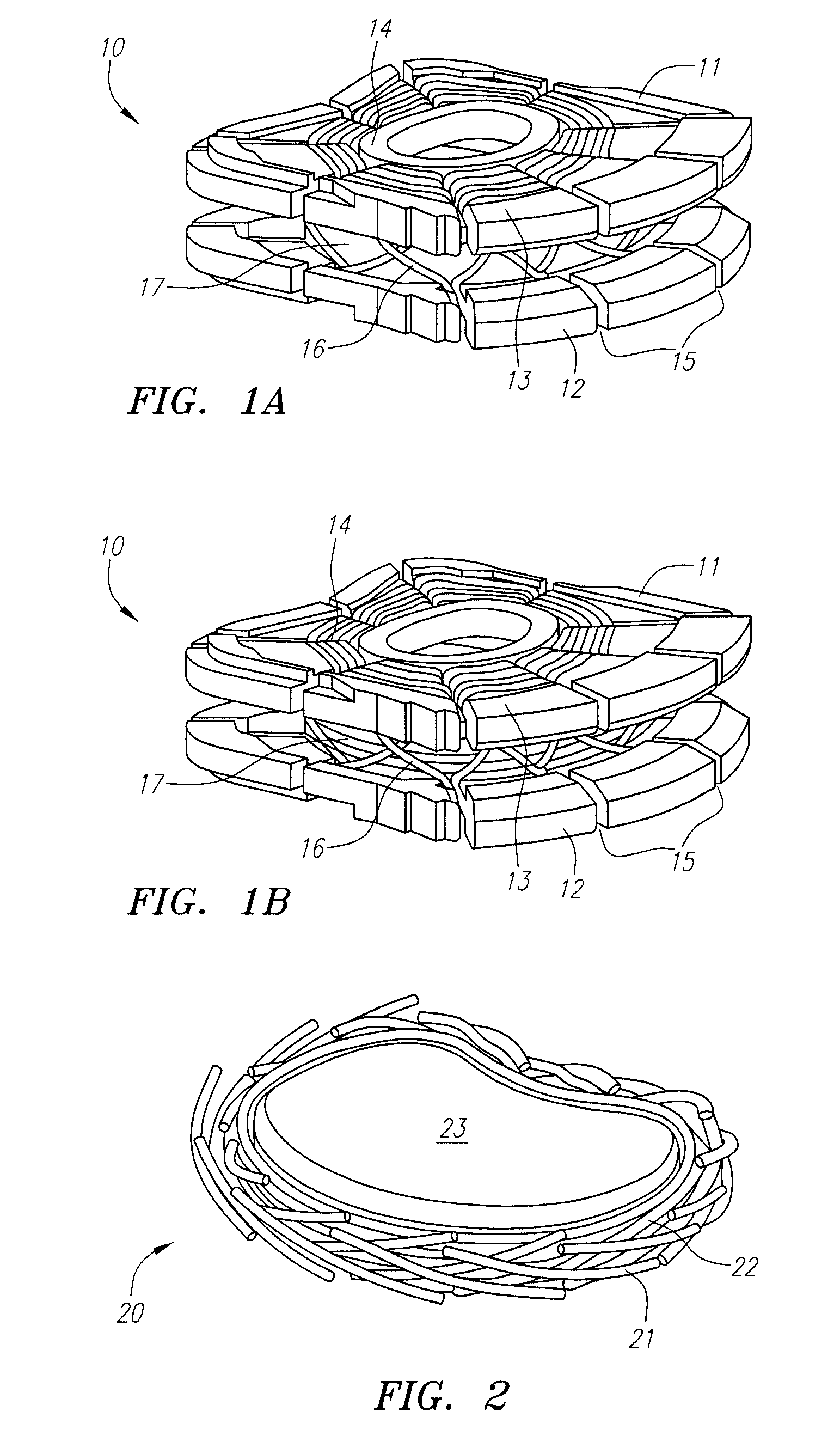
[0012] In several embodiments, the subject prosthetic discs are characterized by including top and bottom endplates separated by a compressible element. The two plates are held together by at least one fiber wound around at least one region of the top endplate and at least one region of the bottom endplate. The fibers are generally high tensile strength fibers with a high modulus of elasticity and high wear resistance. The elastic properties of the fibers, as well as factors such as the number of fibers used, the thickness of the fibers, the number of layers of fiber windings, the tension applied to each layer, and the crossing pattern of the fiber windings enable the prosthetic disc structure to mimic the functional characteristics and biomechanics of a normal-functioning, natural disc. Alternatively, the two plates are held together by an engagement mechanism connecting each plate to the compressible element. The subject discs may be employed with separate vertebral body fixation elements, or they may include integrated vertebral body fixation elements.
[0013] Several optional core materials and structures may be incorporated in each of the prosthetic disc embodiments described herein. For example, the core member may be formed of an appropriately stiff material, such as polyurethane or silicone, and is typically fabricated by injection or compression molding. In other examples, the core member may be formed by layers of fabric woven from fibers. In still further examples, the core member may comprise a combination of these materials, such as a fiber-reinforced polyurethane or silicone. As an additional option, one or more spring members may be placed between the upper and lower endplates in combination with the core member, such as in a coaxial relationship in which the core member has a generally cylindrical or toroidal shape and a spring is located at its center.
[0014] In other embodiments, the core structure comprises two or more core members having different load bearing properties and having the ability to vary the center of rotation of the core structure. The varying properties of the core members may be provided by selection of materials, construction, or other features. In still further embodiments, the core structure comprises one or more core members that are formed of materials or are otherwise constructed to provide varying stiffness or other material properties to accommodate different loads or loading configurations. Examples of these core structures include cores having discrete portions formed of different materials, cores having grooves or other features formed on portions of the core member for other purposes (such as sterilization), and cores having coils or couplers attached to or formed integrally with the core member.
[0015] In still further embodiments, the core structure is provided with one or more mechanisms adapted to adjust the size, shape, orientation, or other feature or combination of features of the core member. For example, the core member may include threads, slots and tabs, or other mechanisms that provide the ability to adjust the height of the core, or to adjust other properties of the core.
[0016] Several particularly preferred core structures include a hollow member that is adapted to be inflated after implantation of the prosthetic disc. In this way, the prosthetic disc is provided with a contracted condition (core uninflated) for delivery and implantation of the disc, and an expanded condition (core inflated) that is adapted for use by the patient after implantation. These core structures may be provided with a fluid port that is adapted to facilitate inflation of the core. Alternatively, a fluid communication lumen may be provided that extends from the hollow core member and provides a lumen through which inflation media may be injected into the core. The hollow core may be provided with two or more compartments, each of which may be independent, or which may be in fluid communication with one another.
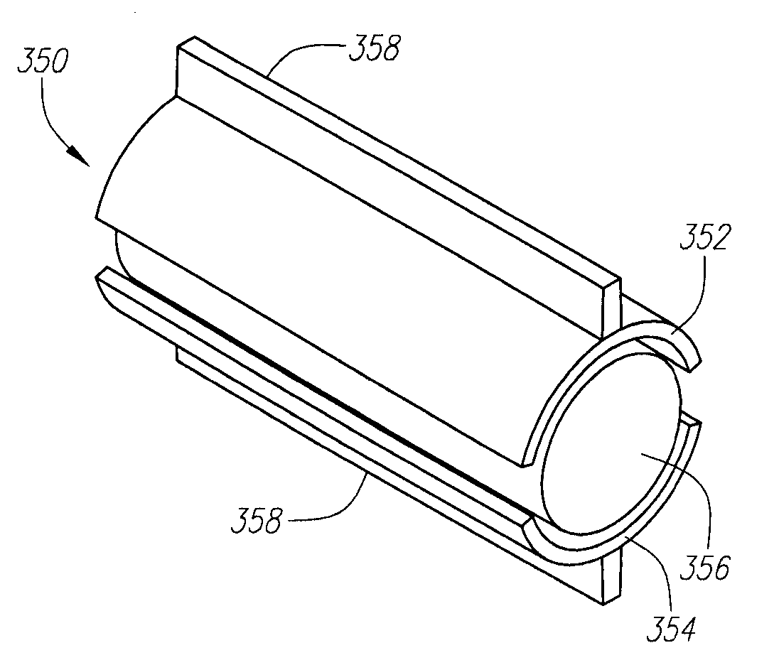
[0017] Several optional endplates and related mechanisms may be incorporated in each of the prosthetic disc embodiments described herein. For example, the endplates may be curved or kidney bean shaped to facilitate rotation of the disc within the intervertebral void space. Alternatively, the endplates may be of a partially cylindrical shape adapted to engage and retain a substantially cylindrical core member.

Problems solved by technology

The spinal disc may be displaced or damaged due to trauma or a disease process.
A herniated or slipped disc may press upon the spinal nerve that exits the vertebral canal through the partially obstructed foramen, causing pain or paralysis in the area of its distribution.
Despite the excellent short-term results of such a “spinal fusion” for traumatic and degenerative spinal disorders, long-term studies have shown that alteration of the biomechanical environment leads to degenerative changes at adjacent mobile levels.
The ball and socket type allows free rotation or movement between the vertebrae between which the disc is installed and thus has no load sharing capability against bending and translation.
(Some ball and socket type artificial discs have rotation limiting features, which still do not address appropriate torque for a natural disc.)
Artificial discs of this type have a very high stiffness in the vertical direction; they cannot replicate the normal compressive stiffness of the natural disc.
Also, the lack of load bearing capability in these types of discs causes adjacent discs to bear the extra load, resulting in the eventual degeneration of the adjacent discs and facets.
These types of discs also cannot replicate a natural disc's instantaneous access of rotation (IAR) as a direct result of lacking natural compressibility.
However, this structure has a problem in the interface between the elastomeric polymer and the metal plates.
Furthermore, the bond of the elastomer to the metal substrate tends to fail after a long usage because of its insufficient shear-fatigue strength.

Method used


Image

  • Prosthetic intervertebral discs
  • Prosthetic intervertebral discs
  • Prosthetic intervertebral discs

Examples


Embodiment Construction

[0052] Before the present invention is described, it is to be understood that this invention is not limited to particular embodiments described, as such may, of course, vary. It is also to be understood that the terminology used herein is for the purpose of describing particular embodiments only, and is not intended to be limiting, since the scope of the present invention will be limited only by the appended claims.

[0053] Where a range of values is provided, it is understood that each intervening value, to at least the tenth of the unit of the lower limit unless the context clearly dictates otherwise, between the upper and lower limit of that range and any other stated or intervening value in that stated range is encompassed within the invention. The upper and lower limits of these smaller ranges may independently be included in the smaller ranges is also encompassed within the invention, subject to any specifically excluded limit in the stated range. Where the stated range include...


PUM


Abstract

Prosthetic intervertebral discs, systems including such prosthetic intervertebral discs, and methods for using the same are described. The subject prosthetic discs include upper and lower endplates separated by a compressible core member. The subject prosthetic discs exhibit stiffness in the vertical direction, torsional stiffness, bending stiffness in the saggital plane, and bending stiffness in the front plane, where the degree of these features can be controlled independently by adjusting the components, construction, and other features of the discs.

Description

RELATED APPLICATION DATA [0001] This application claims priority from U.S. Provisional Application Ser. No. 60 / 713,671, filed Sep. 1, 2005, which application is hereby incorporated by reference in its entirety as if fully set forth herein.BACKGROUND OF THE INVENTION [0002] The intervertebral disc is an anatomically and functionally complex joint. The intervertebral disc is composed of three component structures: (1) the nucleus pulposus; (2) the annulus fibrosus; and (3) the vertebral endplates. The biomedical composition and anatomical arrangements within these component structures are related to the biomechanical function of the disc. [0003] The spinal disc may be displaced or damaged due to trauma or a disease process. If displacement or damage occurs, the nucleus pulposus may herniate and protrude into the vertebral canal or intervertebral foramen. Such deformation is known as herniated or slipped disc. A herniated or slipped disc may press upon the spinal nerve that exits the v...

Claims


Application Information

Patent Timeline
Patent Type & Authority Applications(United States)
IPC IPC(8): A61F2/44
CPCA61F2/30742A61F2250/0028A61F2/442A61F2002/30009A61F2002/30014A61F2002/30075A61F2002/30133A61F2002/30168A61F2002/30179A61F2002/30224A61F2002/30331A61F2002/30387A61F2002/30462A61F2002/30471A61F2002/305A61F2002/30523A61F2002/3055A61F2002/30563A61F2002/30566A61F2002/30576A61F2002/30579A61F2002/30581A61F2002/30586A61F2002/30594A61F2002/30662A61F2002/30884A61F2002/30889A61F2002/30897A61F2002/30899A61F2002/30971A61F2002/4415A61F2002/443A61F2002/448A61F2002/4495A61F2002/4677A61F2002/485A61F2210/0061A61F2220/0025A61F2220/0033A61F2220/0075A61F2220/0091A61F2230/0015A61F2230/0043A61F2230/0058A61F2230/0069A61F2250/0018A61F2/3094A61B17/7062A61B17/7064A61F2/484A61F2/4425A61F2002/444
Inventor REO, MICHAEL L.GITTINGS, DARIN C.
Owner SPINAL KINETICS
Why Eureka
Try Eureka