
Storage system comprising logical circuit configured in accordance with information in memory on PLD

a storage system and information technology, applied in the direction of electronic circuit testing, measurement devices, instruments, etc., can solve the problems of increasing the occurrence rate of soft errors, and reducing the throughput of devices, so as to reduce the effect of throughpu

Inactive Publication Date: 2007-03-01
HITACHI LTD
View PDF2 Cites 22 Cited by
  • Summary
  • Abstract
  • Description
  • Claims
  • Application Information

AI Technical Summary

Benefits of technology

[0008] Therefore, one object of the present invention is to enable a device having a logical circuit configured in accordance with information in a memory located on a PLD to be controlled in a manner which restricts reduction in the throughput of the device in the event of a soft error in the memory.

Problems solved by technology

Therefore, the information in the configuration memory becomes more liable to the effects of radiation, and there is a possibility that the occurrence rate of soft errors may increase.
Consequently, it has become impossible to ignore the occurrence of soft errors.
When a soft error has occurred according to this error monitoring function, then the occurrence of a soft error is reported.
Soft errors that occur may or may not have an actual effect on the configured logical circuit.
However, regardless of this, if a soft error has occurred according to the error monitoring function installed in the FPGA, then the occurrence of a soft error is reported.
Therefore, it is not possible to implement control in accordance with whether or not an occurring soft error actually has an effect on the configured logical circuit.
However, if the main power supply is switched off each time a soft error occurs, then the usability of the device will be poor.
This method is particularly undesirable in cases where the device in which the FPGA is installed is a device which does not permit a long-term halt in operation (namely, a “non-stop device”), and more specifically, for example, a storage system which is required to operate 24 hours a day.

Method used


Image

  • Storage system comprising logical circuit configured in accordance with information in memory on PLD
  • Storage system comprising logical circuit configured in accordance with information in memory on PLD
  • Storage system comprising logical circuit configured in accordance with information in memory on PLD

Examples


Embodiment Construction

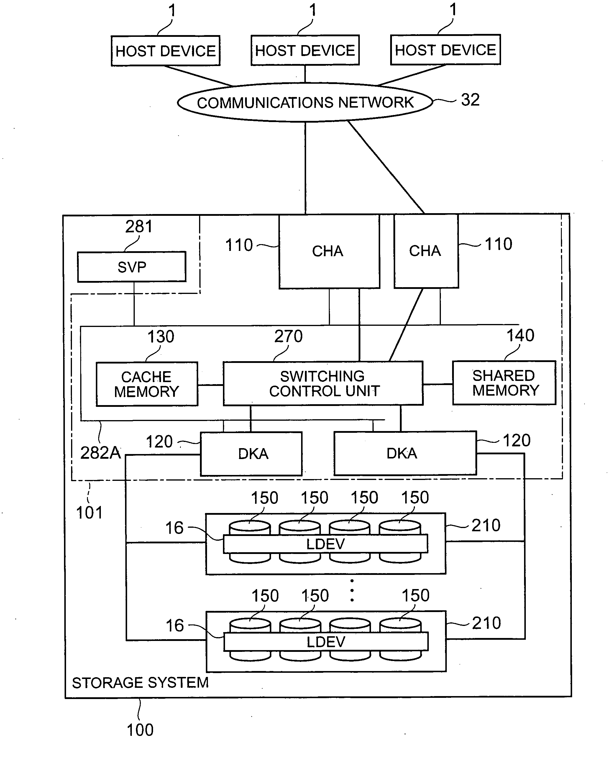
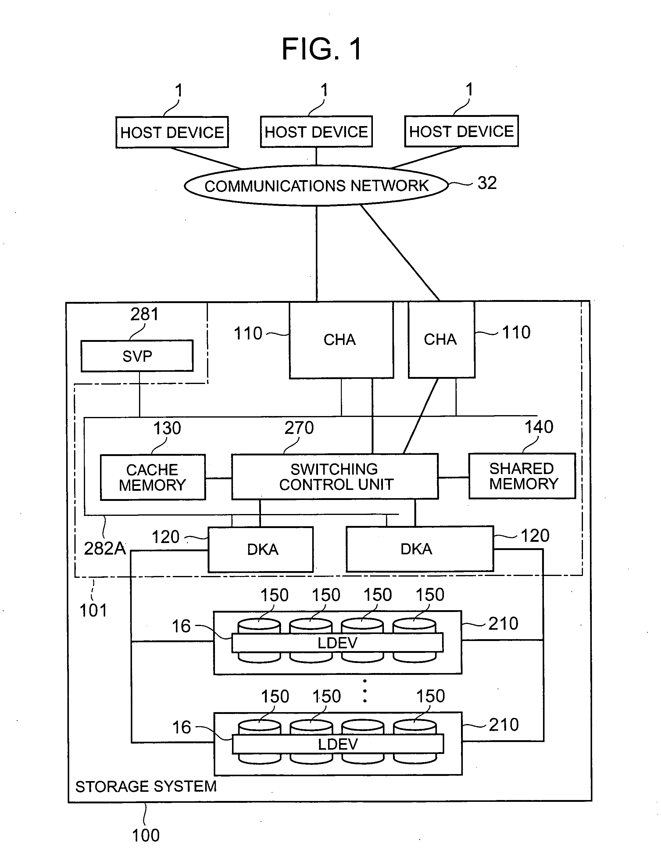
[0030]FIG. 1 is a block diagram showing the general configuration of a storage system relating to one embodiment of the present invention.

[0031] The storage system 100 is connected in a communicable fashion with a plurality of host computers 1, 1, . . . (or one host computer 1), via a communications network (for example, a SAN (Storage Area Network)) 32.

[0032] The storage system 100 is a disk array device, such as a RAID (Redundant Array of Independent Disks), for example. The storage system 100 comprises, for example, a control unit 101 for controlling the processing carried out by the storage system 100, a RAID group 210, and a service processor (SVP) 281. The control unit 101 comprises, for example, one or a plurality of disk adapters (hereinafter, “DKA”) 120, one or a plurality of channel adapters (hereinafter, “CHA”) 110, a cache memory 130, a shared memory 140 and a switching control section 270.

[0033] The RAID group 210 comprises a plurality of HDD (hard disk drives) 150; ...


PUM


Abstract

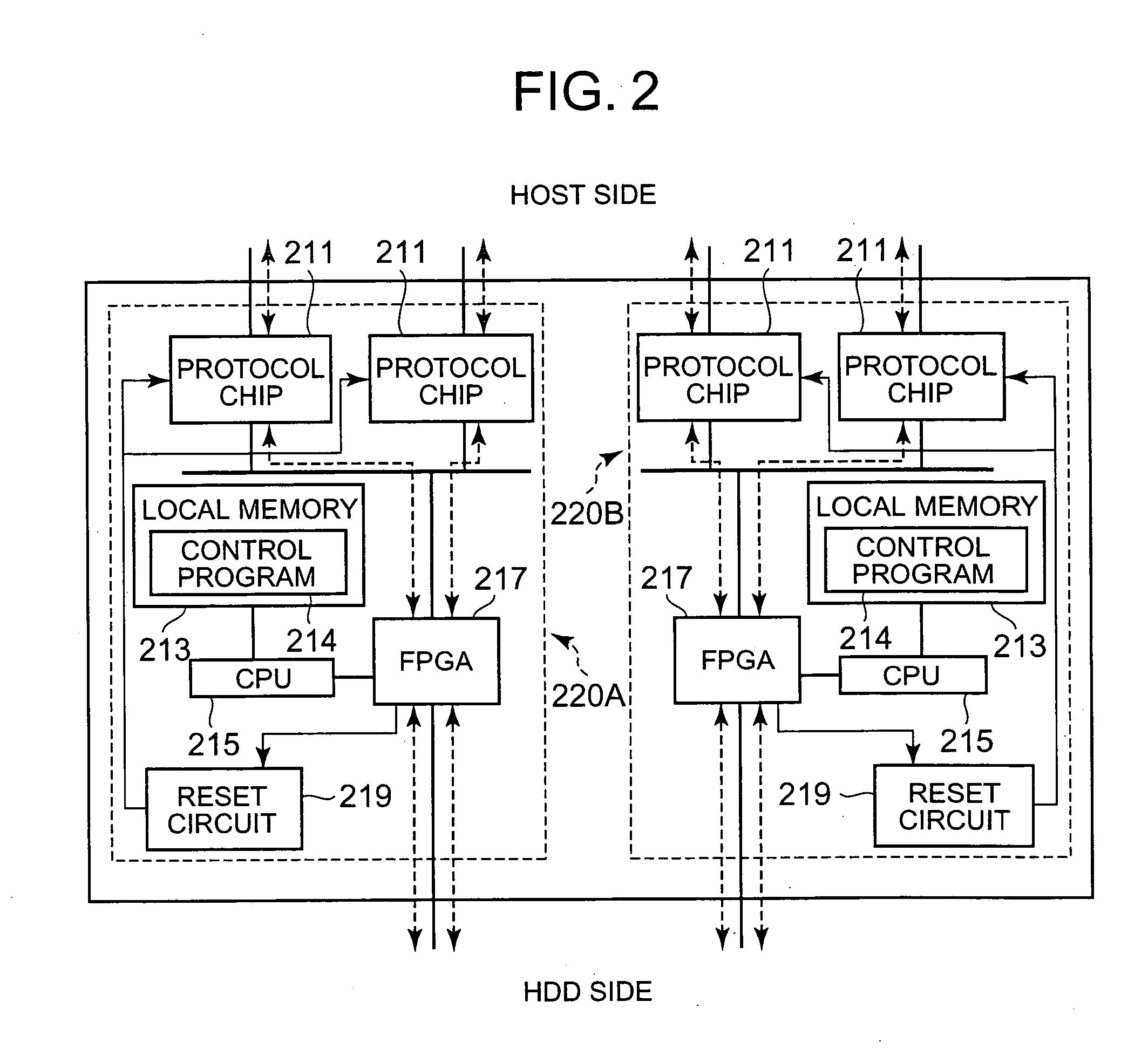
The storage system comprises a PLD which controls data transfer between another device and a media drive; and a processor. The PLD comprises a memory for storing information input from an information source located externally to the PLD; a circuit element group comprising a plurality of circuit elements; and a logical circuit configured on the circuit element group in accordance with the information in the memory. The processor detects whether a soft error has occurred in the memory, detects whether or not an error has occurred in the logical circuit, and implements control in accordance with the results of the two detection operations.

Description

CROSS-REFERENCE TO PRIOR APPLICATION [0001] This application relates to and claims priority from Japanese Patent Application No. 2005-241198, filed on Aug. 23, 2005 the entire disclosure of which is incorporated herein by reference. FIELD OF THE INVENTION [0002] The present invention relates to technology for controlling a device provided with a logical circuit configured in accordance with information in a memory on a PLD (Programmable Logic Device) BACKGROUND OF THE INVENTION [0003] Conventionally, it is known that information in a memory can be corrupted (for instance, a bit stating “1” may change to “0”), in other words, a soft error may occur, due to a cause such as an α beam or a neutron beam being irradiated onto the memory (see, for example, Japanese Patent Laid-open No. 8-137764). [0004] A type of PLD is known which allows configuration of a logical circuit having a configuration indicated by circuit configuration information contained in a memory (information indicating th...

Claims


Application Information

Patent Timeline
IPC IPC(8): G11C29/00
CPCG01R31/31816G11C2029/0409G11C2029/0401G11C29/52
Inventor SASAKURA, TAKAHIRO
Owner HITACHI LTD
Learn More