
Magnetically attractable components for self-sizing jewelry articles

a technology of magnets and components, applied in the field of magnets, can solve the problems of not being able to secure jewelry components together, not being able to achieve the magnetic strength of precious metal magnets, and not being able to achieve the magnetic strength of maximum strength, and minimizing gaps between adjacent dimensioning members

Inactive Publication Date: 2007-03-08
KRETCHMER STEVEN +1
View PDF41 Cites 3 Cited by
  • Summary
  • Abstract
  • Description
  • Claims
  • Application Information

AI Technical Summary

Benefits of technology

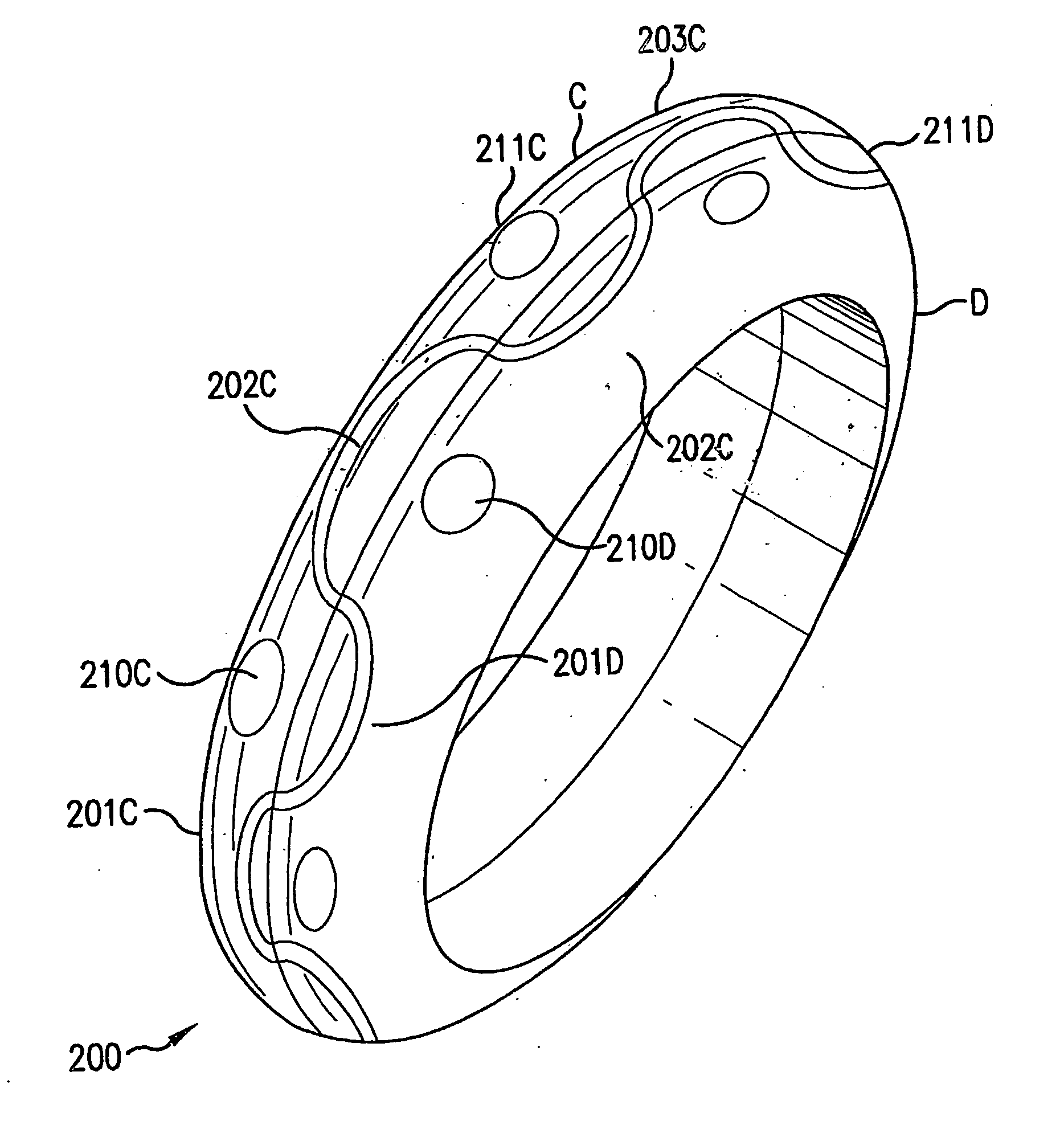
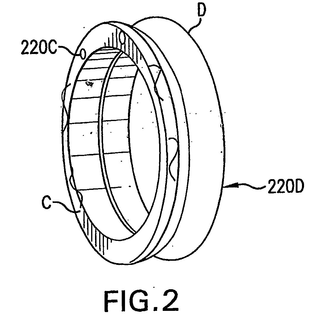
"The present invention relates to a magnetic jewelry-forming component for preparing jewelry articles. The component has a body member with a first magnetizable portion that can be attracted to another magnetic jewelry-forming component using a magnet. The body member has a curved or arcuate surface, an annular configuration or ring shape. The component can be adjusted to conform to the wearer's hand strength and can be magnetically joined to other components in different positions. The invention allows for the creation of jewelry articles with magnetically attracted components that can be easily adjusted to fit different wearers."

Problems solved by technology

Such permanent magnets are generally made of non-precious metal alloys and for that reason are not desirable for use in fine jewelry.
While there have been some attempts at making precious metal magnets, two problems have been encountered.
Many precious metal magnets do not possess sufficient magnetic strength to secure jewelry components together.
Furthermore, attempts at alloying such metals to increase their magnetic strength causes excessive dilution of the precious metal content of the alloy, thus rendering it less desirable for use in jewelry components or articles.
A magnetized platinum cobalt alloy is known, but previously has not been deemed to be suitable for use in jewelry components or articles.
In addition, highly magnetic jewelry articles can be problematic in certain situations.
Contact of strong magnets with credit cards, computer disks or other magnetically sensitive materials can cause damage to such materials.
Also, rings, bracelets and necklaces, if strongly magnetized, are generally located such that they can easily come in contact with magnetically sensitive materials to cause damage or loss of information therein.
It is often difficult to properly size the ring so that it can be snugly maintained in place as it must also be sufficiently large to pass over the person's knuckles, especially for people that have arthritic joints.
This means that the ring must be sized larger to accomplish this and then will be too loose when in the proper position.
Also, the person's finger can change in size over the years, and a ring that is correctly sized at one time can end up being incorrectly sized in the future.
The accommodation of different sizes creates difficulties for the jewelry manufacturer and seller, in that different sizes must be made available, or specialized orders must be custom made to the person's actual or desired dimensions.

Method used


Image

  • Magnetically attractable components for self-sizing jewelry articles
  • Magnetically attractable components for self-sizing jewelry articles
  • Magnetically attractable components for self-sizing jewelry articles

Examples


Embodiment Construction

[0045] The term “loop” is utilized herein to refer to a final article that has no beginning and no end, i.e., a ring, oval, polygon or like configuration. This loop can partially or fully arcuate or can have straight or linear portions therein. It also can be configured as a tube of any cross sectional configuration.

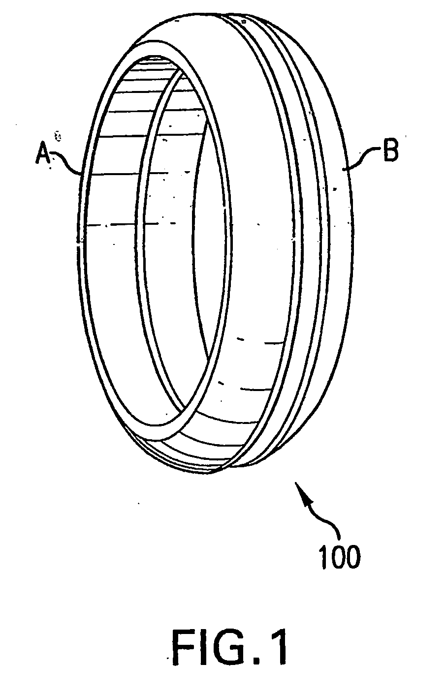
[0046]FIG. 1 illustrates a typical split finger ring 100 having two symmetrical ring portions A, B and being in a joined condition. In this embodiment, the split ring is provided in two portions, each magnetized with opposing polarities so that the portions are magnetically attracted to each other. In use, the portions are held together by magnetic force. Even so, the magnetic strength of the joined components can be overcome by had force. The components can be separated much more easily by applying a shearing force rather than by trying to pull apart the components in directly opposite directions. For this reason, it is sometimes useful to design a flange or other rete...


PUM


Abstract

A magnetic jewelry-forming component for preparing a jewelry article. The article includes a body member configured and dimensioned in an ornamental shape and having a first magnetizable portion for attractive or repulsive magnetic association with at least one other magnetic jewelry-forming component and at least one further element for magnetically coupling to the at least one other magnetic jewelry-forming component. Advantageously, the body member has a magnetic strength that can be overcome by a person's hand strength such that the body member and at least one other magnetic jewelry forming component can be placed in different positions relative to each other. Also, the further element includes (a) a second magnetized portion that has a polarity that is different from that of the at least one other magnetic jewelry-forming component so that it is magnetically attracted thereto or (b) a retaining structure that prevents complete separation of the body member from the at least one other magnetic jewelry-forming component when the first magnetized portion of the body member has a polarity that is the same as that of the at least one other magnetic jewelry-forming component so that it is magnetically repulsed therefrom. These components enable the jewelry article to be self-sizing by repulsion or attraction, to include the use of multiple fields to reduce damaging magnetic emanations from the article, or to control position or motion of the components in the article to provide highly desirable and unusual jewelry articles.

Description

BACKGROUND ART [0001] The invention relates to jewelry components that are magnetized and joined to form new and unusual jewelry articles having heretofore unknown properties and advantages. [0002] In particular, the present invention relates to jewelry components that are magnetically attractable to or repulsed by each other so a plurality of such components can be joined or combined into rings, bracelets, chains, chokers, necklaces, earrings, watchbands or the like, with the magnetic force holding the components together or apart, as desired. Also, components can be connected in any one of a number of positional relationships so that the final jewelry article is self-sizing to the wearer. [0003] Jewelry articles are generally made of different types of precious metals and stones and are held together by mechanical linkages or interconnections. This is of course well known to the skilled artisans and in common use today. Designers are somewhat limited by these mechanical connection...

Claims


Application Information

Patent Timeline
Patent Type & Authority Applications(United States)
IPC IPC(8): A44C5/00A44C5/20A44C9/02
CPCA44C5/0092A44C5/2057A44D2203/00A44C9/02A44C5/22
Inventor KRETCHMER, STEVENSTUPAK, JOSEPH JOHN
Owner KRETCHMER STEVEN
Learn More