Adjustable flow liquid dispenser

a liquid dispenser and adjustable technology, applied in liquid transferring devices, instruments, volume meters, etc., can solve the problems of increasing the cost of retail and commercial consumers of dispensing systems, increasing food safety risks for users (especially in multiple user environments), and reducing storage and point of use space. , the effect of improving efficiency

Inactive Publication Date: 2007-03-08
FLEET PHILIP B +3
View PDF51 Cites 18 Cited by
  • Summary
  • Abstract
  • Description
  • Claims
  • Application Information

AI Technical Summary

Benefits of technology

[0013] It is another object of the present invention to eliminate the need for multiple bottles, and therefore reduce storage and point of use space required to deliver a wide range of flavor options, which also improves efficiency and reduces cost.
[0014] It is yet another object of the present invention to incorporate easily removable and replaceable cartridges with a user-controlled blend-selection dial, allowing for widely variable flavor and heat combinations for different cuisines (e.g. BBQ, Mexican Asian, Indian, etc.), the differing taste buds of communal users (e.g. different appreciation or tolerance for spicy foods) and / or the varied moods of one user.
[0015] It is yet another object of the present invention to reduce food safety risks due to handling issues by placing a finger-activated dial and pump away from the delivery spout and by including a cap or other cover mechanism to minimize manual contact with the spout.
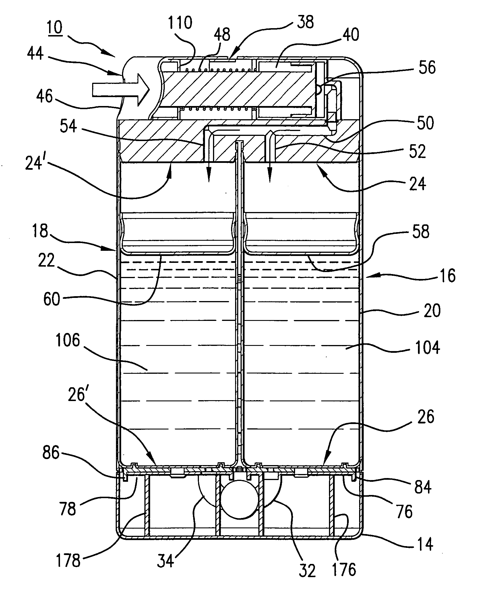
[0016] It is still another object of the present invention to provide a sauce (or other liquid) dispensing bottle (which is considered to be durable), with at least two replaceable inner cartridges (which are considered to be disposable), filled with product(s) of varying flavor and viscosity, with a control means (such as a circular dial), by which the user can select the desired blend (i.e., heat intensity for hot sauce uses) by adjusting the numerical selection on the dial and pushing a button or pump to initiate the extraction and delivery of the sauce. Upon actuation of the pump, compressed air is forced over the cartridge-resident pistons such that the proper portions of liquid are issued through each cartridge's metering discs and delivered via an internal set of conduits and co-axial exit orifice (which the user directs as desired onto food). The dispensing system is conceived to allow the user to visibly determine, at all times and without separate action, which type of cartridges are resident and the remaining volume of the product in each of the replaceable cartridges. In addition, the dispensing system is arranged to prevent dispensing when the user's selection requires product from a cartridge which is empty or missing. The dispensing control means will provide an “off” condition whereby no product will be dispensed from any cartridge. This “off” condition will also allow for safe cartridge removal and replacement without risk of spillage. The metering control means as conceived allows complete and full variation from zero to full flow for each replaceable cartridge, based on the user-selected increments on the dial. The pump element allows the user to control the delivered volume of end product, and provides a slight pull-back vacuum to help prevent dripping or product-buildup within the coaxial dispensing opening (which could taint the next user's selection.) The dispensing system is designed to be a closed and sterile system; as such, the delivery orifice is conceived to be closed or behind moveable closure. As much as possible, the delivery system (its manifold and delivery orifice) is to be designed to allow storage and use in any orientation.

Problems solved by technology

This increases the cost for retail and commercial consumers of dispensing systems and therefore is a negative aspect of conventional food flavoring sauce dispensing systems known in the art.
Additionally, many conventional food dispensing systems expose users (especially in multiple user environments) to increased food safety risks due to handling issues, such as fingers touching the exit orifice during removal or replacement of the cap or during rotation of a spout valve.

Method used


Image

  • Adjustable flow liquid dispenser
  • Adjustable flow liquid dispenser
  • Adjustable flow liquid dispenser

Examples


Embodiment Construction

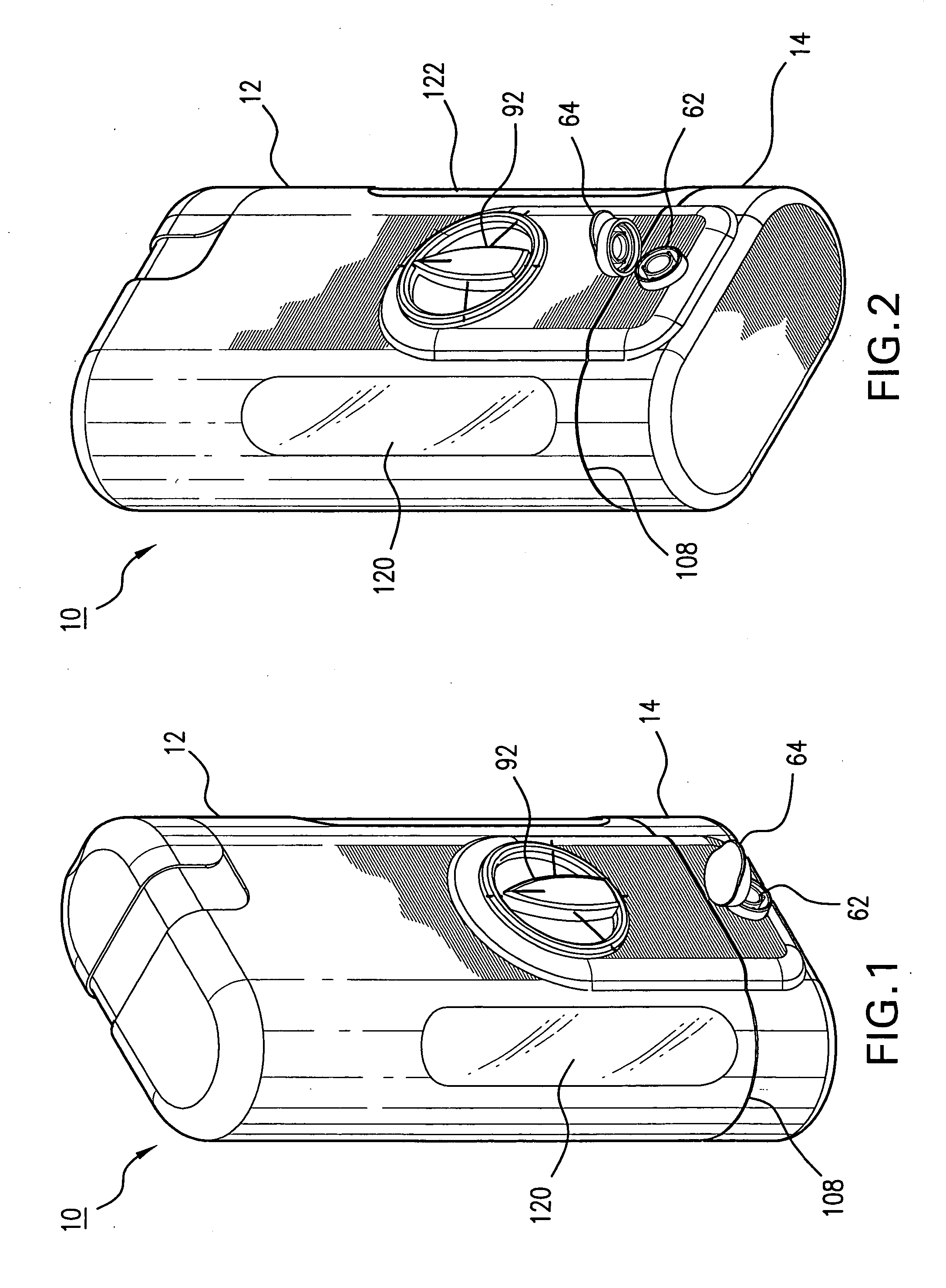
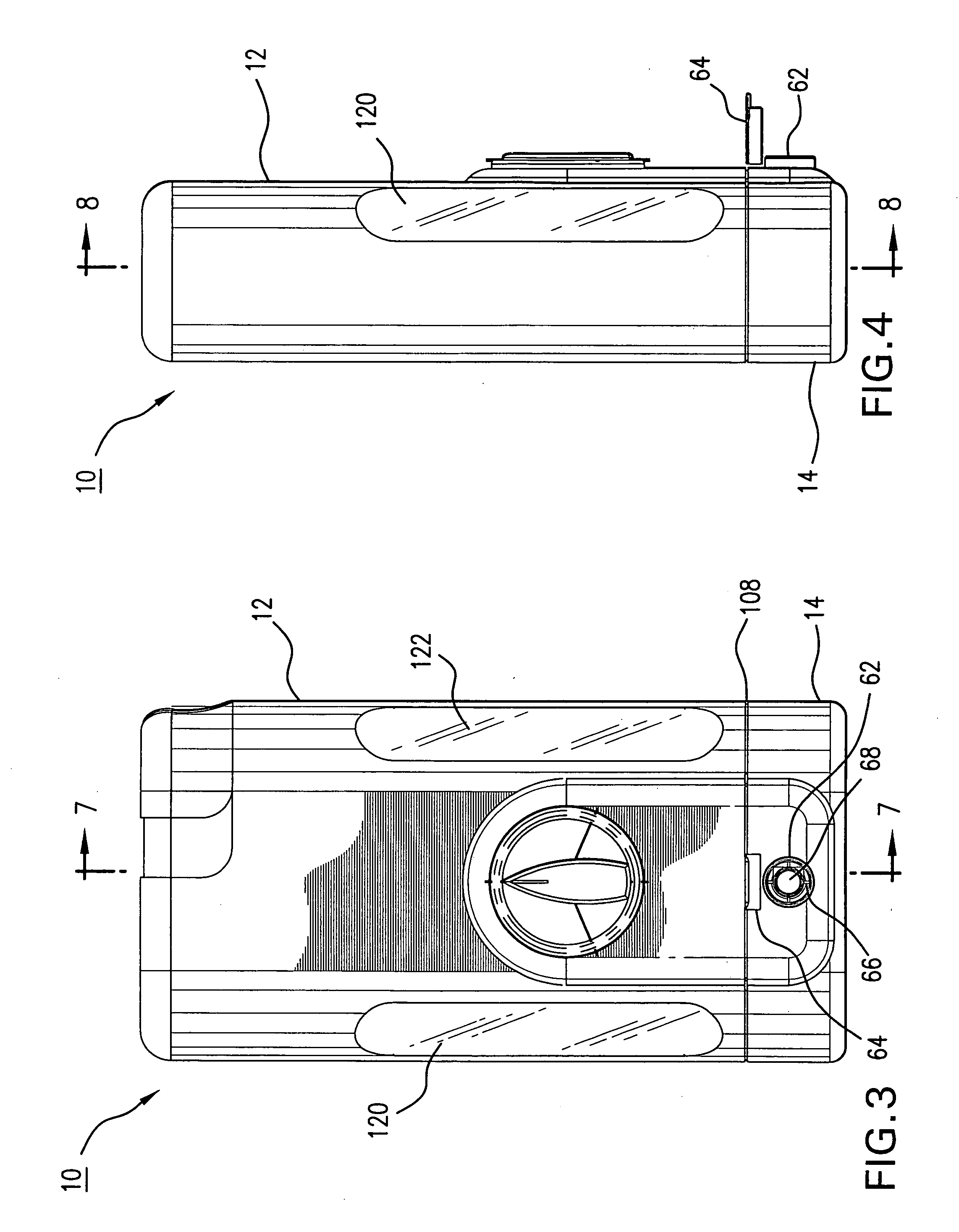
[0034] Referring now to FIGS. 1-17, there is shown adjustable and selective dispensing system 10 for dispensing at least two flowable liquid materials 104, 106 through a coaxial dispensing opening 62 clearly shown in FIGS. 1 and 2. As will be further described, the user selects his or her desired ratio of liquid materials 104, 106 by rotating selection knob 92 and then initiates delivery of this desired composition by using the pump assembly 38 to create air pressure necessary to force movable pistons within cartridges 20 and 22 to impart pressure upon liquid materials 104 and 106, also resident within cartridges 20 and 22, thereby forcing the liquid materials 104, 106 through a flow metering mechanism, also to be further described, before the desired ratio of liquid material 104, 106 ultimately exits the dispensing system 10 through the coaxial dispensing opening 62.

[0035] Cartridges 20 and 22, which are disposable and replaceable, and which contain respective viscous liquid mater...


PUM


Abstract

An apparatus that is an adjustable and selective dispensing system for dispensing at least two flowable materials, and into which can be inserted a set of cartridges containing the flowable materials. Each cartridge has a piston end and a metering end. Each cartridge includes a moveable piston at its piston end driven by compressed air pressure created by actuating a pump assembly also resident in the dispensing system. The dispensing system also contains a set of metering discs, one of which adjoins each of the cartridges at the metering end thereof, for selectively dispensing the flowable materials from the cartridges. There are a set of conduits adjacent each of the metering discs for providing a predetermined amount of the flowable materials to be dispensed. A metering control mechanism rotationally actuating the metering discs for controlling the flow of the flowable materials from each of the cartridges is also provided.

Description

REFERENCE TO RELATED APPLICATIONS [0001] This patent application is based upon Provisional Application Ser. No. 60 / 714,352 filed 7 Sep. 2005.BACKGROUND OF THE INVENTION [0002] 1. Field of the Invention [0003] The present invention is directed to a reusable and variably adjustable dispensing system for multiple food products for retail (consumer home and travel) and commercial (restaurant and institutional) use. [0004] 2. Description of the Prior Art [0005] Multiple food flavoring sauces and containers for dispensing the sauces currently exist. However, the vast majority of these embodiments are designed for delivery of one sauce at a time. With these existing containers, the user controls the intensity of the result solely by varying the volume dispensed and / or varies the flavor by combining multiple products from multiple dispensers, all in a relatively imprecise manner. [0006] Existing food flavoring sauce dispensers typically require or suggest total replacement when empty. This ...

Claims


Application Information

Patent Timeline
Patent Type & Authority Applications(United States)
IPC IPC(8): B67D5/52G01F11/00B67D7/70
CPCB01F13/002B01F13/0022B65D81/325B01F15/0265B01F15/0203B05B7/061B05B11/0032B05B11/02B05B11/06B05B12/1409B05B12/1418B05B1/3026B05B11/0054B01F33/50111B01F33/5011B01F35/712B01F35/71825B05B11/1083B05B11/1097
Inventor FLEET, PHILIP B.NORWOOD, MARK D.REILLY, DONALD P.MACLEAN-BLEVINS, MARK T.
Owner FLEET PHILIP B
Why Eureka
Try Eureka