Positional sensing system and method

a sensing system and sensing technology, applied in the field of positional sensing system and method, can solve the problems of limiting the utility of conventional grating-based encoders, high cost of calibrated gratings, and affecting the use of optical detection devices

Inactive Publication Date: 2007-03-08
ROMANOV NIKOLAI L +1
View PDF24 Cites 41 Cited by
  • Summary
  • Abstract
  • Description
  • Claims
  • Application Information

AI Technical Summary

Problems solved by technology

Conventional grating-based encoders suffer from various limitations that restrict their utility.
One limitation is the high cost of calibrated gratings.
This cost is elevated due to the necessities of high precision fabrication, the use of stable (e.g., thermally stable) materials, and the functional relationship between cost and length (since longer encoders require commensurately longer gratings.
Currently, encoders cost several hundred dollars per meter per axis in mass quantities.
Absolute encoders are typically more expensive than incremental ones due to the increased complexity.
Another limitation associated with conventional linear encoders is their sensitivity to scratches, damage, and contamination.
Yet another limitation associated with conventional linear encoders is their limited ability to provide extremely fine resolution, particularly without substantially increased cost.
Any optical lens or system has a viewing angle that results in undesirable scale change relative to the object distance from the lens.
A typical commercial telecentric lens has a viewing angle of 0.2 degree. Such a viewing angle, while small, still causes a perceptible scale change that limits the measuring accuracy and affect the mounting tolerances for an optical system.
Tullis suffers from certain limitations that restrict its utility.
A device according to Tullis may have insufficient speed at high-resolution operation to be suited for use with target surfaces of extended length.
The unique and identifiable patterns taught by Tullis for providing absolute position measurement may also have limited application to high-resolution target surfaces of extended length.
Furthermore, Tullis fails to address potential problems associated with surface alteration.
Additionally, Tullis describes the use of telecentric lenses (which limit measuring accuracy).

Method used


Image

  • Positional sensing system and method
  • Positional sensing system and method
  • Positional sensing system and method

Examples


Embodiment Construction

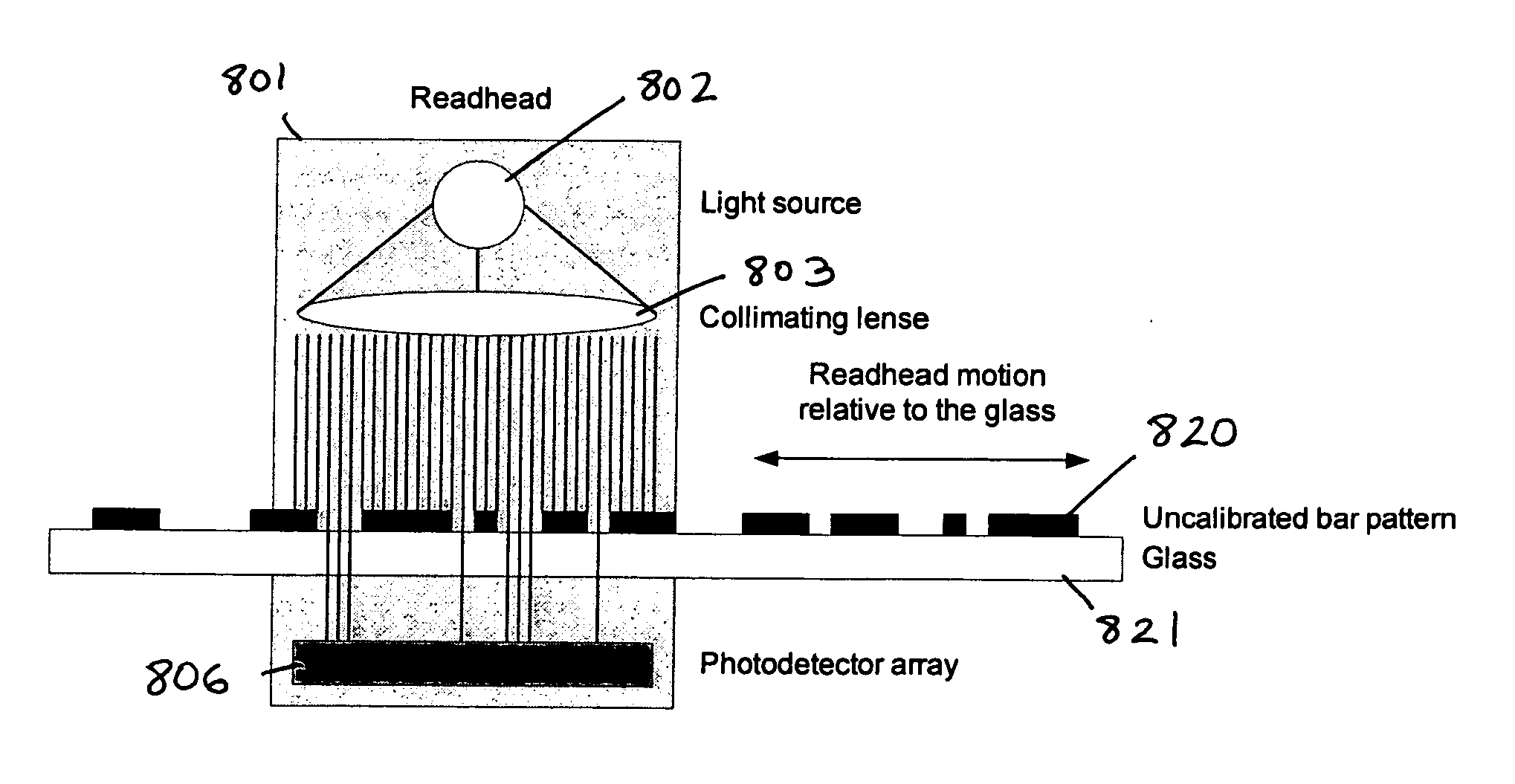
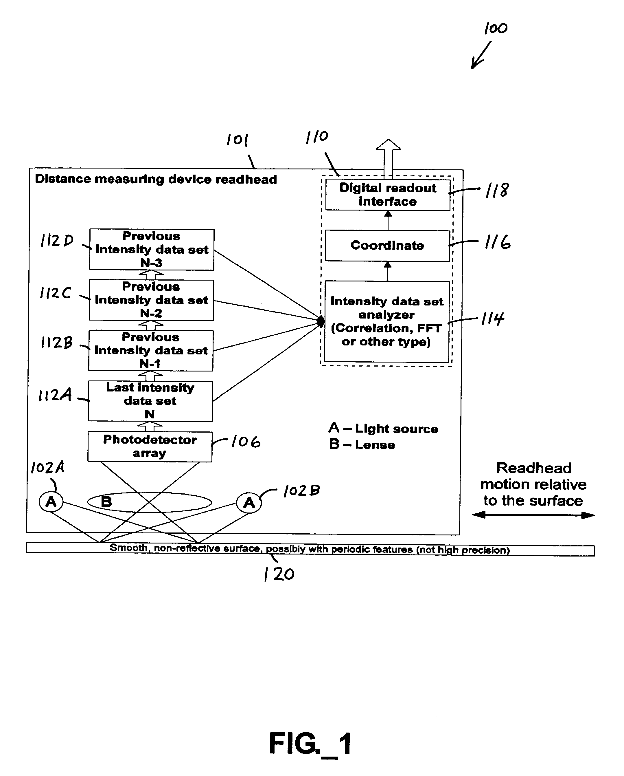
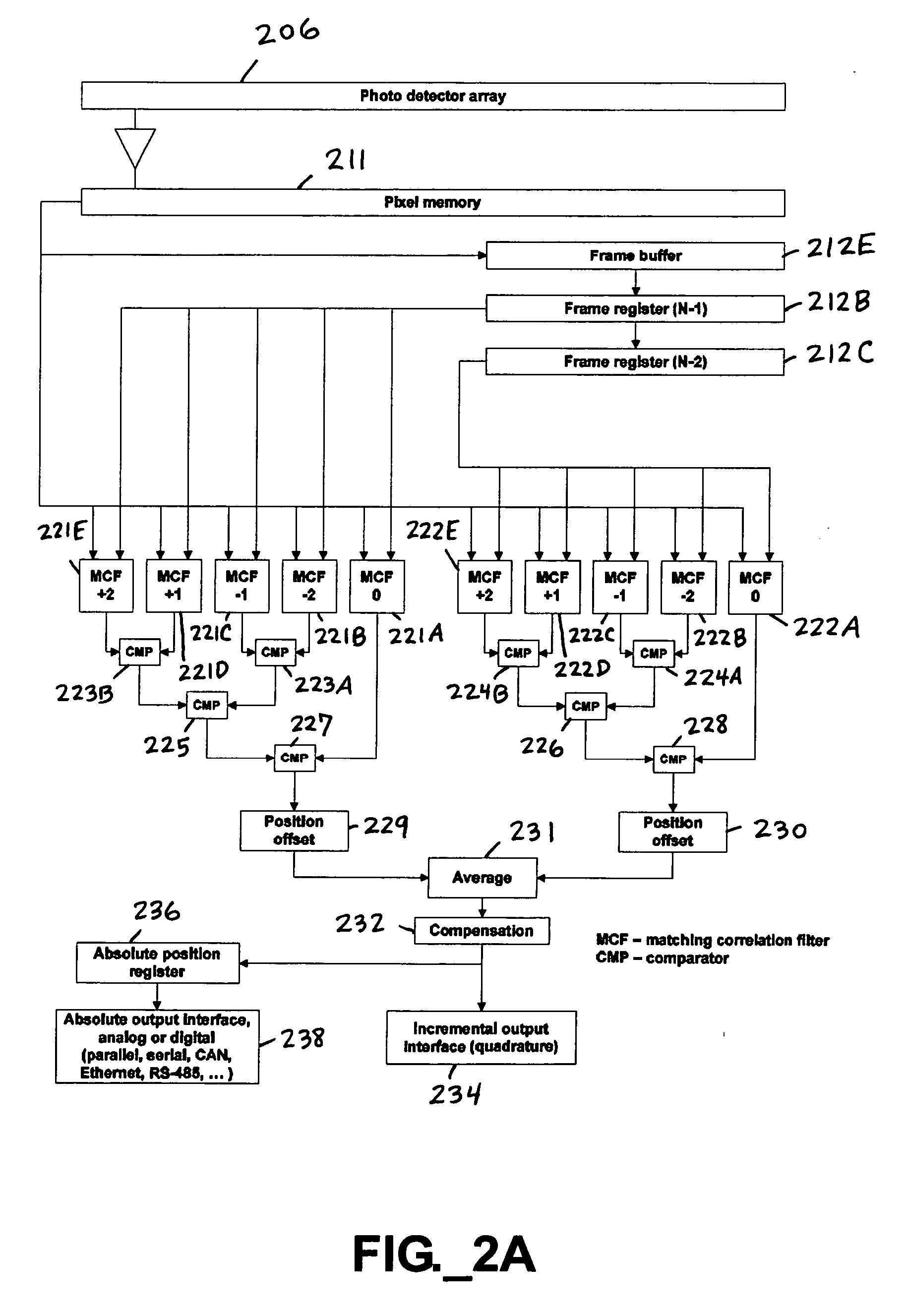
[0026] Certain embodiments of the invention are directed to positional sensing systems utilizing real-time pattern analysis and positional determination, utilizing an uncalibrated patterned surface. The term “uncalibrated patterned surface” as used herein refers to any surface having surface features, whether inherent or introduced, perceptible (e.g., at a sufficient signal-to-noise ratio) to an imaging device, without requiring calibration and present in amount or spatial density sufficient to provide a desired dimensional resolution utilizing the inventive positional sensing systems and methods described herein. The attainable resolution of the positional sensing systems described herein depends in part on the quality and perceptibility of the surface features. The patterned surface may include a patterned film, such as a self-adhesive patterned film, applied to an underlying surface. The pattern may be regular or irregular, with the patterned surface preferably consisting of suba...


PUM

PropertyMeasurementUnit
viewing angleaaaaaaaaaa
incidence angleaaaaaaaaaa
displacementaaaaaaaaaa

Abstract

Systems and methods adapted for use with uncalibrated patterned surfaces for sensing any of position, displacement, velocity, acceleration, area, and volume are provided. A system includes a memory, processing electronics, and at least one readhead adapted to move relative to the surface and including a radiation source, lens, and an optical array transducer. One aspect includes generating a mapping data set representative of an intensity map of the patterned surface. Another aspect provides a variable travel speed readhead. Other aspects include multiple readheads adapted to travel in concert. Incremental and absolute sensing are provided, including systems having sub-pixel spatial resolution.

Description

CROSS-REFERENCE TO RELATED APPLICATIONS [0001] The benefit of priority of U.S. Provisional Application No. 60 / 715,051 filed Sep. 7, 2005 in the names of Nikolai L. Romanov and Dmitri A. Kossakovski for “Linear Imaging Encoder,” and U.S. Provisional Application No. 60 / 741,755 filed Dec. 2, 2005 in the names of Nikolai L. Romanov and Dmitri A. Kossakovski for “Positional Sensing System and Method,” is hereby claimed under the provisions of under 35 USC 119(e).BACKGROUND OF THE INVENTION [0002] 1. Field Of The Invention [0003] This invention relates to systems and methods for sensing any of position, displacement, velocity, acceleration, area, and volume. Such systems and methods may be useful in industrial automation, microscopy, surface profiling, scanning, printing, material deposition, and metrology. [0004] 2. Description Of The Related Art [0005] Linear encoders are used to measure variable linear positions of industrial machinery and generate output signals of these positions, ra...

Claims


Application Information

Patent Timeline
Patent Type & Authority Applications(United States)
IPC IPC(8): G01N21/86G01D5/34G01V8/00
CPCG01D5/2495G01D5/34715G01V8/20G01P3/68G01P3/806G01P3/36
Inventor ROMANOV, NIKOLAI L.KOSSAKOVSKI, DMITRI A.
Owner ROMANOV NIKOLAI L
Why Eureka
Try Eureka