Superconducting circuit for generating pulse signal

a superconducting circuit and pulse signal technology, applied in pulse generators, pulse manipulation, pulse techniques, etc., can solve the problems of high precision, high difficulty in providing delay, and difficult high-frequency signal propagation through such signal lines, and achieve small jitter and high precision.

Inactive Publication Date: 2007-03-08
FUJITSU LTD +1
View PDF2 Cites 37 Cited by
  • Summary
  • Abstract
  • Description
  • Claims
  • Application Information

AI Technical Summary

Benefits of technology

[0033] According to at least one embodiment of the present invention, a first Josephson junction and second Josephson junction having different threshold values are provided in a superconducting loop, with one of the junctions being used to preset a single flux quantum and the other junction being used to reset the single flux quantum. Provision of different threshold values between the first Josephson junction and the second Josephson junction makes it possible that each Josephson junction is switched on only once in one cycle of the alternating-current input to generat

Problems solved by technology

It is difficult, however, to supply a high-frequency signal from a semiconductor circuit operating in a room temperature environment to a superconducting circuit operating in a low temperature environment.
This is because the signal line is required to have a long length and a narrow width in order to suppress heat propagation through the signal line, and it is difficult for the high-frequency signal to propagate through such a signal line.
It is difficult, however, to provide a delay with high precision for the JTL at each stage of the ladder circuit, and, also, there is a

Method used


Image

  • Superconducting circuit for generating pulse signal
  • Superconducting circuit for generating pulse signal
  • Superconducting circuit for generating pulse signal

Examples


Embodiment Construction

[0043] In the following, embodiments of the present invention will be described with reference to the accompanying drawings.

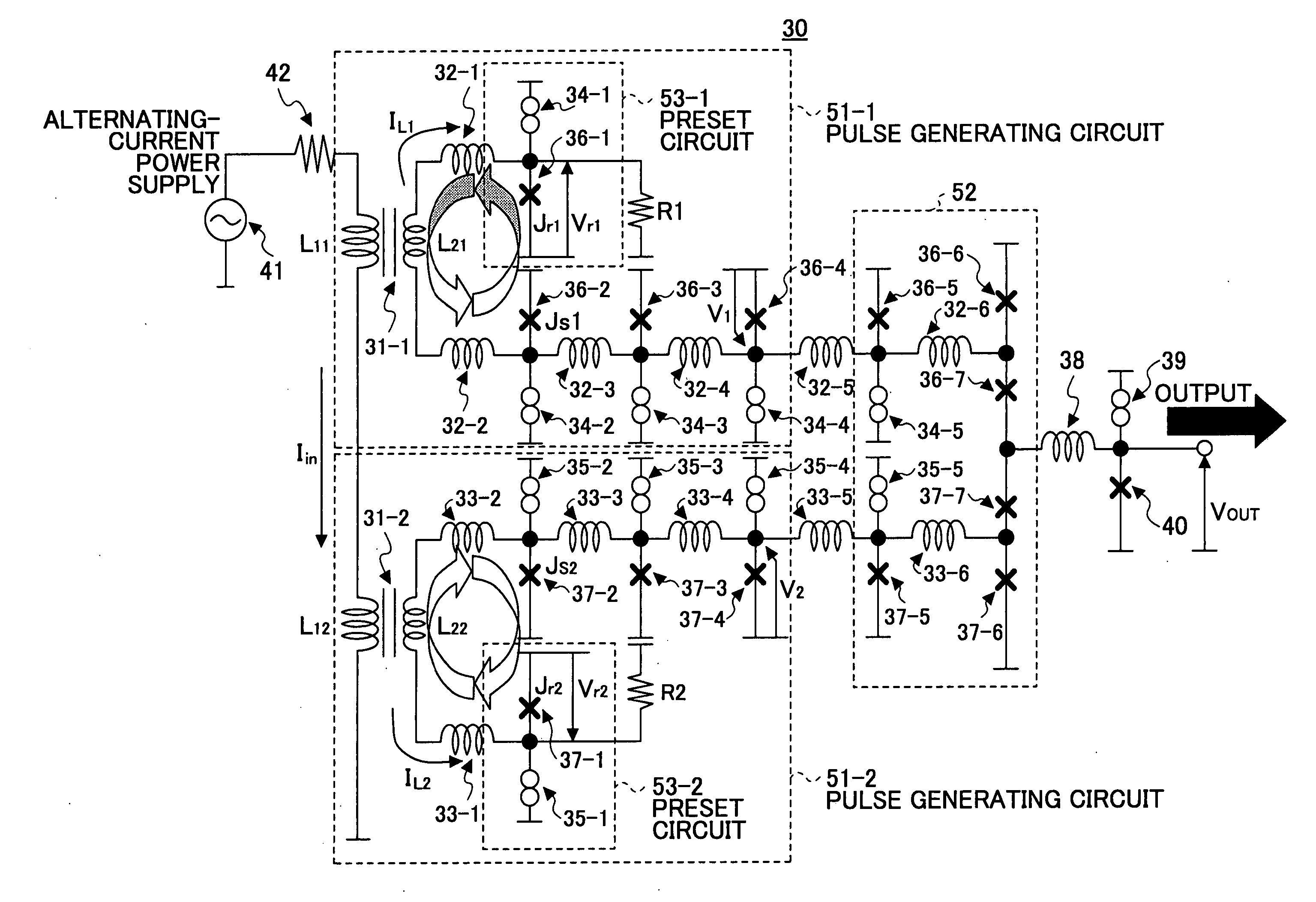
[0044]FIG. 3 is a drawing showing the configuration of an embodiment of a clock generating circuit according to the present invention. A clock generating circuit 30 shown in FIG. 3 includes a transformer circuit 31-1, a transformer circuit 31-2, inductors 32-1 through 32-6, inductors 33-1 through 33-6, bias-purpose current sources 34-1 through 34-5, bias-purpose current sources 35-1 through 35-5, Josephson junctions 36-1 through 36-7, Josephson junctions 37-1 through 37-7, a resistor R1, a resistor R2, an inductor 38, a bias-purpose current source 39, and a Josephson junction 40. The primary-side inductor L11 of the transformer circuit 31-1 and the primary-side inductor L12 of the transformer circuit 31-2 receive a sinusoidal electric current Iin from an alternating-current power supply 41 through a resistor 42.

[0045] The transformer circuit 31-1, the inducto...


PUM


Abstract

A superconducting circuit includes a first transformer to produce a first alternating-current output at a secondary-side inductor, a second transformer to produce a second alternating-current output at a secondary-side inductor, a first pulse generating circuit to produce a single flux quantum pulse responsive to the first alternating-current output, a second pulse generating circuit to produce a single flux quantum pulse responsive to the second alternating-current output, and a confluence buffer circuit to merge the single flux quantum pulses from the pulse generating circuits, wherein each of the pulse generating circuits includes a superconducting loop including the secondary-side inductor, a first Josephson junction situated in the superconducting loop to generate the single flux quantum pulse, and a second Josephson junction situated in the superconducting loop, a threshold value of the second Josephson junction for an electric current flowing through the secondary-side inductor being different from that of the first Josephson junction.

Description

CROSS-REFERENCE TO RELATED APPLICATIONS [0001] The present application is based upon and claims the benefit of priority from the prior Japanese Patent Application No. 2005-256585 filed on Sep. 5, 2005, with the Japanese Patent Office, the entire contents of which are incorporated herein by reference. BACKGROUND OF THE INVENTION [0002] 1. Field of the Invention [0003] The present invention generally relates to superconducting circuits utilizing a single flux quantum, and particularly relates to a superconducting circuit that generates a high-frequency clock through frequency multiplication. [0004] 2. Description of the Related Art [0005] As a macroscopic quantum effect of superconductor, a loop formed by superconductor results in magnetic flux being quantized within the loop. The minimum unit of magnetic flux that is quantized in superconductor is called an SFQ (single flux quantum). An SFQ circuit is a logic circuit that operates with magnetic flux quantum serving as information car...

Claims


Application Information

Patent Timeline
IPC IPC(8): H03K19/195
CPCH03K3/38H03K12/00H03K5/12H03K5/00006
Inventor TAGUCHI, ATSUSHIHIMI, TAKUYASUZUKI, HIDEOYOSHIDA, AKIRATANABE, KEIICHI
Owner FUJITSU LTD
Why Eureka
Try Eureka