Image processing method and computer readable medium for image processing

a technology of image processing which is applied in the field of image processing method and computer readable medium for image processing, can solve the problems of loss of correspondence between the regions, inability to obtain abnormal phase, and difficulty in detecting abnormal phase by the method, so as to achieve the effect of reducing the calculation amoun

Active Publication Date: 2007-03-08
ZIOSOFT
View PDF3 Cites 7 Cited by
  • Summary
  • Abstract
  • Description
  • Claims
  • Application Information

AI Technical Summary

Benefits of technology

[0018] According to the described configuration, a comparison is made between the structure information respectively obtained from each of the volume data so as to detect the anomaly in the structure information. Thus, need for performing calculations of motion compensation, precise region extraction, etc., as in the related art is eliminated, so that the anomaly in images corresponding to the plurality of phases can be detected in small calculation amounts.
[0020] According to the described configuration, region extraction is executed using the path information of a vessel, etc., the surface information of the surface of an organ, etc., and the coordinate information of the center coordinates of a tissue, etc., so that the calculation amount to detect a failure part can be decreased and a precise image can be created in a short time.
[0022] According to the described configuration, the group of volume data includes the time-series data, and the structure information of the preceding phase and the subsequent phase of the time-series data are used for determination of the anomaly, so that processing for detecting the anomaly in the structure information is simplified.
[0024] According to the described configuration, the region information is generated from the structure information, and when an abnormal phase is detected, the structure information corresponding to the abnormal phase is re-calculated, so that a precise image can be created in a short time with a small calculation amount.
[0026] According to the invention, a comparison is made between the structure information respectively obtained from a plurality of groups of the volume data so as to detect the phase having an anomaly. Thus, a need for performing calculations of motion compensation, precise region extraction, etc., as in the related art is eliminated, so that the calculation amount can be decreased in detecting an anomaly in images corresponding to a plurality of phases.

Problems solved by technology

However, when deformation of the organ occurs while photographing, the abnormal phase cannot be obtained.
This is because the differential region is obtained by making a comparison of raster data, and thus particularly when time resolution of a moving image is insufficient, correspondence between the regions is lost.
For example, when a vessel moves in an image, and any part of the vessel does not exist in the same coordinates for each phase, continuity of raster data in the time direction does not exist and therefore it is difficult to detect the abnormal phase by the method in the related art.
Therefore, it is difficult to make a comparison between the extraction results in other phases so as to detect an error.
Therefore, a great deal of calculation time and user labor for checking are taken, and the image of the region of interest cannot be displayed with good responsivity.
In the image processing method in the related art, the regions are compared directly as raster data, and thus particularly with respect to volume data, calculation amount increases and it becomes difficult to perform the registration.
Therefore, it is difficult to perform a correction of region extraction result when the organ is being deformed in time series just by using the preceding and subsequent phases.
Therefore, extraction failure parts are often generated as shown in phase 2 of the actual extraction results in FIG. 8B.
Furthermore, most of registration algorithms require some region extraction result itself, in the processing process.
It is difficult to provide sufficient registration in a state in which the region extraction result is not obtained.

Method used


Image

  • Image processing method and computer readable medium for image processing
  • Image processing method and computer readable medium for image processing
  • Image processing method and computer readable medium for image processing

Examples


first embodiment

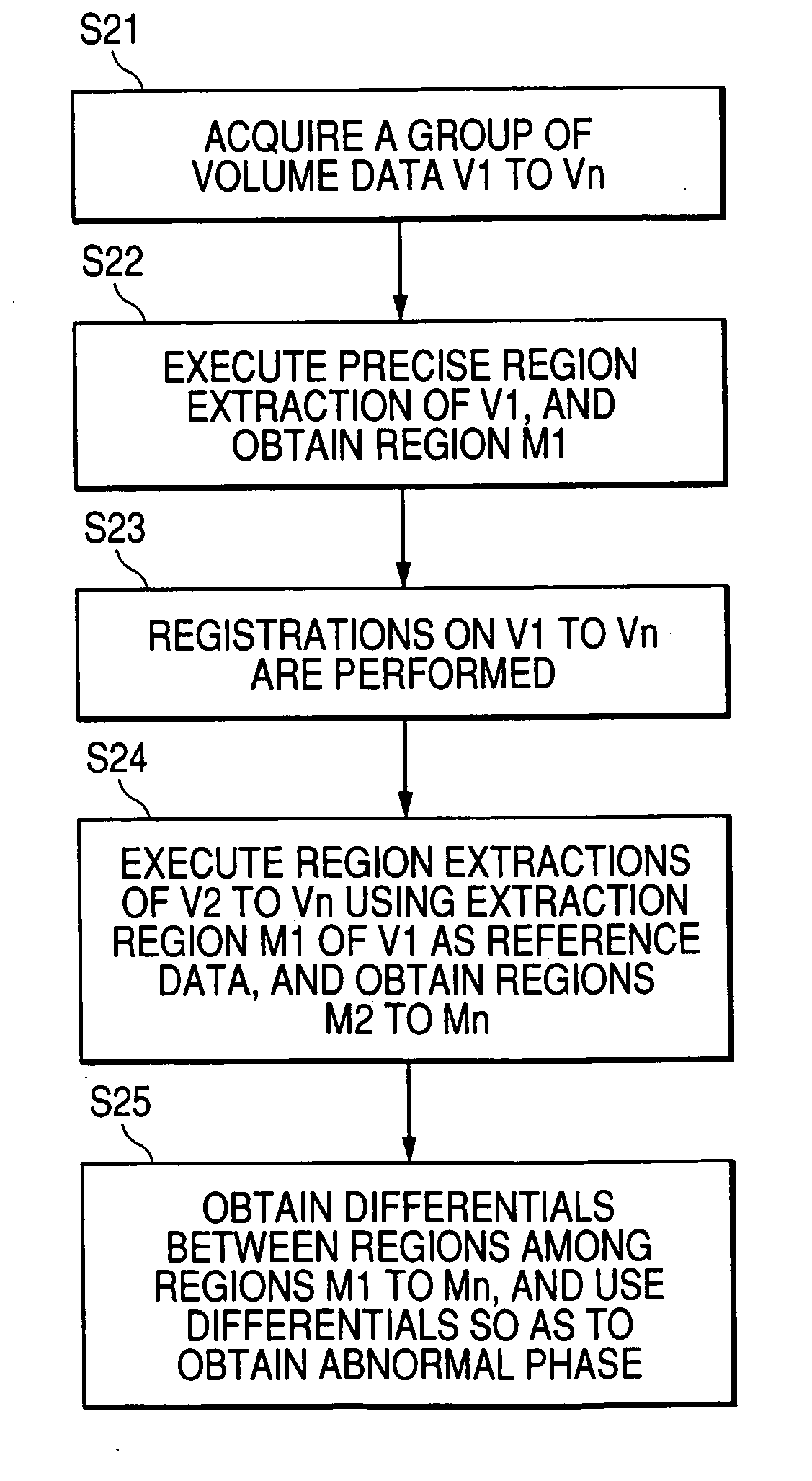
[0038]FIG. 1 shows a case where a region of interest of a heart and a vessel, for example, is extracted in the image processing method of a first embodiment. From image data in each phase, the region is extracted using an existing method (3D region growing method, etc.,) and a mask representing the extraction region is created. That is, region N−1 is extracted in phase N−1, region N is extracted in phase N, and region N+1 is extracted in phase N+1.

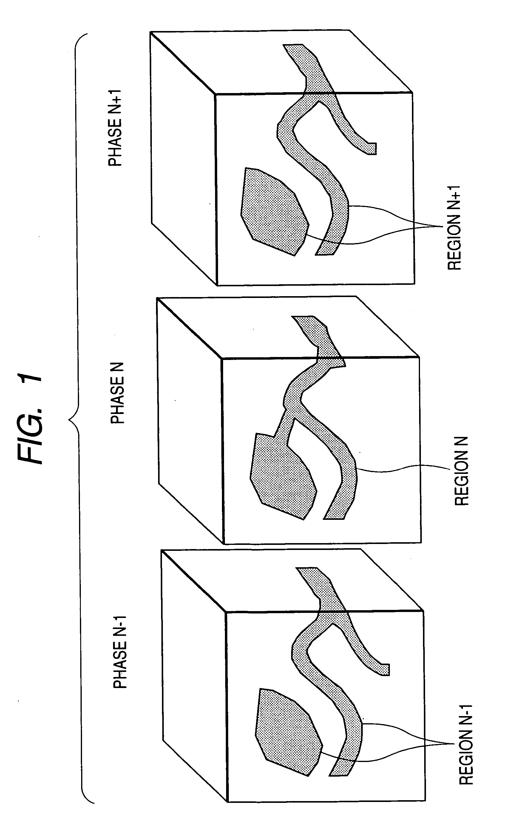
[0039] Next, structure information of a tissue is calculated from the extraction result. FIG. 2 shows how the structure information is calculated by performing skeltonization on the extraction regions, and a tree-like path (graph) is obtained in the image processing method of the embodiment. That is, structure information N−1 representing a center line of the vessel, etc., is calculated from the data in phase N−1, structure information N is calculated from the data in phase N, and structure information N+1 is calculated from the data in p...

second embodiment

[0046]FIG. 4 shows how a failure in the region extraction is detected by detecting changes in the coordinates of a tissue in the image processing method of a second embodiment. For example, range coordinates of an extraction region or coordinates of the center of gravity of the region are obtained in each phase. That is, the range coordinates (x1-x2, y1-y2, z1-z2) (from x1 to x2, from y1 to y2, from z1 to z2) of an extraction region or the coordinates of the center of gravity (x3, y3, z3) of the region are obtained in the phase N−1, and the range coordinates (x5-x6, y5-y6, z5-z6) of an extraction region or the coordinates of the center of gravity (x4, y4, z4) of the region are obtained in the phase N.

[0047] In this case, when the region extraction results in failure, the coordinates of the center of gravity (x4, y4, z4) and the range coordinates (x5-x6, y5-y6, z5-z6) largely move as shown in the phase N. Accordingly, a failure in the region extraction is detected. In addition, a co...

third embodiment

[0049]FIG. 5 shows how a failure in the region extraction is detected by detecting changes in surface information of a tissue in the image processing method of a third embodiment. For example, number of surfaces is detected for each phase, or heterogeneous topology like a surface included in a surface is detected for each phase, and a comparison is made in the preceding and subsequent phases. When the number of surfaces or the topology changes in the preceding and subsequent phases, a failure in the region extraction is detected.

[0050] According to the image processing method of the embodiment, when the structure information of the number of surfaces, the topology, etc., in the preceding and subsequent phases change, namely, when an anomaly in the structure information is detected, a failure in the region extraction is detected. Thus, reliability of the region extraction result can be determined. Since the re-calculation of the region extraction of the failure part can be performed...


PUM


Abstract

Failure part is detected using calculated structure information. In one embodiment, the failure part is detected by comparing path node positions, numbers of node positions, branch lengths, and branch positions. That is, it is detected that although nodes a2 and a3 exist in structure information N in phase N, corresponding nodes do not exist in the preceding phase N−1 or the subsequent phase N+1. Moreover, it is detected that a node a1 existing in the preceding phase N−1 and a node a5 existing in the subsequent phase N+1 do not exist in a corresponding part a4 in the structure information N in the phase N.

Description

[0001] This application claims foreign priority based on Japanese Patent application No. 2005-256883, filed Sep. 5, 2005, the content of which is incorporated herein by reference in its entirety. BACKGROUND OF THE INVENTION [0002] 1. Field of the Invention [0003] This invention relates to an image processing method and a computer readable medium for image processing for generating an image of a lesion part, an organ, etc., from volume data obtained by various image diagnosis apparatuses such as an X-ray CT (Computed Tomography) apparatus and an MRI (Magnetic Resonance Imaging) apparatus for medical use. [0004] 2. Description of the Related Art [0005] Various image diagnosis apparatuses such as the X-ray CT apparatus and the MRI apparatus generate tomographic images of an inspection part from the volume data of a subject, and display an image on a monitor screen for diagnosis. For example, in a case of an organ of a circulatory system such as a heart or a vessel or any other moving o...

Claims


Application Information

Patent Timeline
Patent Type & Authority Applications(United States)
IPC IPC(8): G06K9/00
CPCG06T7/0012G06T7/0081G06T7/602G06T2207/30101G06T2207/10076G06T2207/20044G06T2207/30048G06T7/606G06T7/11G06T7/62G06T7/66
Inventor MATSUMOTO, KAZUHIKO
Owner ZIOSOFT
Why Eureka
Try Eureka