
Implantable shunt system and method

a shunt and implantable technology, applied in the field of implantable shunt systems and methods, can solve the problems of imbalance between production and absorption, high system pressure, and high shunt failure rate, and achieve the effect of preventing the high rate of shunt failur

Inactive Publication Date: 2007-03-08
BOARD OF RGT THE UNIV OF TEXAS SYST
View PDF7 Cites 6 Cited by
  • Summary
  • Abstract
  • Description
  • Claims
  • Application Information

AI Technical Summary

Benefits of technology

[0017] The new shunting system should be effective in preventing the high rate of shunt failure in the patient population with intraventricular hemorrhage. The shunting system also allows early shunting and the rapid mobilization of patients out of an ICU setting with all.the advantages, both medical and financial, that this would entail.

Problems solved by technology

Any increase in this amount rapidly increases the pressure in the system.
Anything which interferes with the normal re-absorption of CSF will rapidly cause an imbalance between production and absorption, and will quickly throw off the homeostasis of the system.
The problem of managing this condition typically-is complicated by the poor clinical condition of these patients.
This clotting quite rapidly leads to an increase in the intraventricular volume and pressure, eventually leading to an increase in intracranial pressure.
In some patients, there is only a temporary need for ventricular drainage as the hydrocephalus steaming from the intraventricular hemorrhage is self-limited.
Those patients who develop hydrocephalus and require a ventriculo-peritoneal shunt (VP) placement, have limited absorption of cerebral spinal fluid (CSF) secondary to the scarring caused by the hemorrhage, as well as obstruction in the normal flow of CSF caused by the scarring.
During this time, a VP shunt cannot be placed because the blood in the ventricular system will clog the delicate valve mechanisms in the shunt system.
This extended stay in an intensive care setting represents a two-fold problem.
First and most importantly, it is a large risk to the patients who often could otherwise be in a less invasive setting with less potential for infection and other complications, such as a normal ward or a rehabilitation ward.
Second, this extended stay represents a large drain on the resources of the facility and the general health system.
Although this initially appeared promising, it has had limited application because of the risk of worsening of the intraventricular hemorrhage associated with the thrombolytics.
This has the risk of over drainage of the ventricular system with both short term and long term risks.
This strategy places the patient at risk of acute over drainage with its potential catastrophic effects, as well as long term over drainage with alterations in the intracranial pressure (ICP) dynamics.
Another strategy for management of the intraventricular blood has been the use of opened intracranial surgery where the surgeon physically removes the intraventricular blood has been met with generally poor results, and is not felt to be an adequate strategy for the management of this problem.
Unfortunately, they also have not had great success in accomplishing the goal of adequately removing the intraventricular blood.
Although this portion of the shunt fails more commonly than does the ventricular catheter, it seldom fails as a result of mechanical issues of the apparatus, and more often due to physiologic limitations relating to the terminus chosen.
As a result, especially in patients with intraventricular hemorrhage where the CSF has a great deal of blood in it, the valves often fail as they become obstructed with debris.

Method used


Image

  • Implantable shunt system and method
  • Implantable shunt system and method

Examples


Embodiment Construction

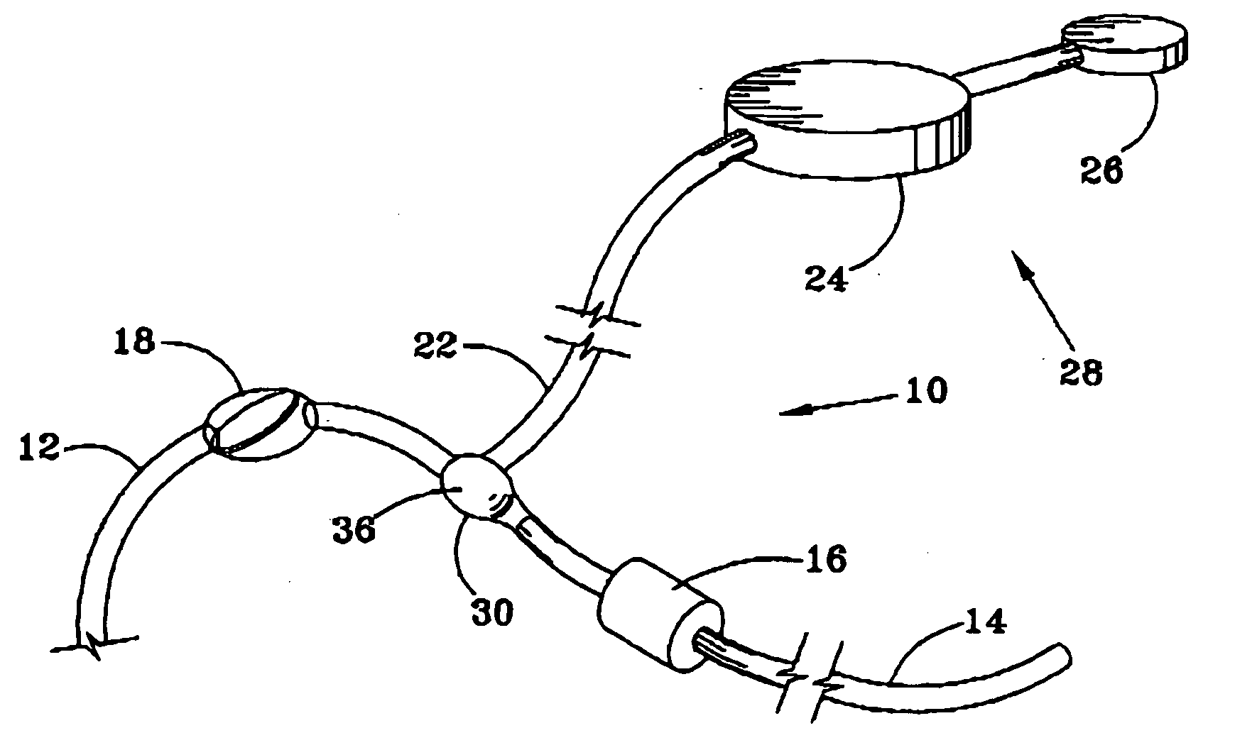
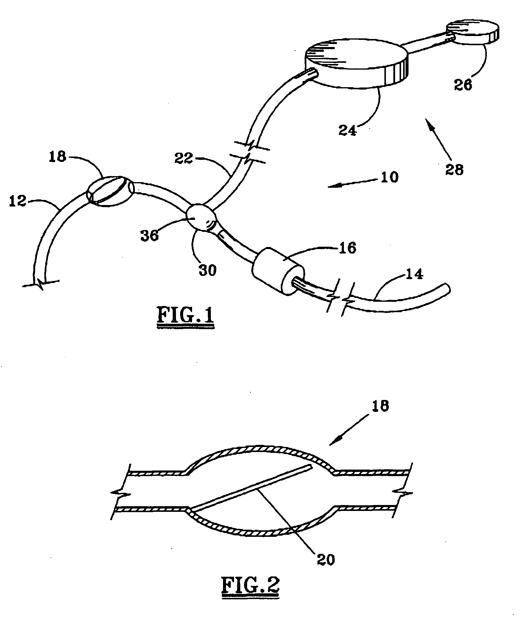
[0021] The new shunt system 10 utilizes some of the components of existing shunt systems, namely a brain ventricular catheter 12, a distal or downstream catheter 14, and a regulating valve 16, and adds new components in order to overcome the problems particular to the patient population with significant blood in the CSF and its propensity for clogging existing shunt systems. The catheter 12 is positioned for draining fluid from the brain ventricle, and the distal catheter 14 passes the fluid to a selected terminus within the patient's system, such as the peritoneal cavity, the pleural cavity, the pleural cavity, or the blood circulation system. The shunt system function will be independent of the type of regulating valve mechanism utilized and therefore independent of the valve manufacturer. Each catheter preferably includes a sylastic tube.

[0022] In order to overcome the problem of the propensity for obstruction of the valve system with blood and debris, the blood is broken down p...


PUM


Abstract

An implantable shunt system 10 and method include a ventricle catheter 12 for insertion into the brain ventricle, a distal catheter 14 for insertion into a selected terminus in the patient, and a regulating valve 16 for controlling flow through the distal catheter. An implantable pump 24 delivers a liquid thrombolytic solution upstream from the regulating valve, and a check valve 18 prohibits flow through the check valve in the direction toward the brain ventricle. A storage reservoir or chamber 26 is provided for containing the thrombolytic agent.

Description

FIELD OF THE INVENTION [0001] Many intracranial problems are complicated by the development of intraventricular hemorrhage and secondary hydrocephalus. These problems, regardless of their original etiology, have a common feature of blood in the cerebral ventricular system and secondary hydrocephalus. The present invention provides a more effective treatment strategy for these problems. BACKGROUND OF THE INVENTION [0002] Anatomically, the cerebral spinal fluid (CSF) is contained throughout the entire central nervous system. CSF is produced primarily in the lateral, third and fourth ventricles of the brain. It essentially represents an ultrafiltrate of plasma, and in non-disease states does not contain cells or protein. CSF is distributed through out the central nervous system and is held primarily in three different compartments: the ventricles, the subarachnoid space and the lumbar thecal sac. These compartments are in fluid communication and are maintained in a state of homeostasis...

Claims


Application Information

Patent Timeline
Patent Type & Authority Applications(United States)
IPC IPC(8): A61M5/00
CPCA61M27/006A61M2202/0464A61M39/24
Inventor GORMLEY, WILLIAM B.
Owner BOARD OF RGT THE UNIV OF TEXAS SYST
Learn More