
Digital stereotaxic manipulator with controlled angular displacement and fine-drive mechanism

Inactive Publication Date: 2007-03-08
SCOUTEN CHARLES W +2
View PDF3 Cites 47 Cited by
  • Summary
  • Abstract
  • Description
  • Claims
  • Application Information

AI Technical Summary

Benefits of technology

[0068] In the second enhancement, a “fine-drive” mechanism is added to the system, to provide an operator with more precise control over motion of an instrument. This can be done by mounting a radial gear to the main threaded vertical shaft in the vertical arm assembly, and providing a helical gear on a newly-added horizontal shaft. Rotation of the helical gear can be used to drive the radial gear, which will slowly rotate the main vertical shaft. If a 1:20 gearing ratio is provided by the fine-drive gears, this provides an operator with 20-times more precise control over vertical (dorsal-ventral) motion of an instrument. A spring-loaded detente mechanism is also provided, to enable the fine drive mechanism to pop out of position without damaging anything, if an operator attempts to rotate the main vertical control knob before disengaging the fine-drive mechanism.

Problems solved by technology

Although the word “test” is occasionally used by some to refer to such procedures, in many situations the actual test(s) that will evaluate the effects of a surgical, drug injection, or other procedure may not be carried out until days, weeks, or even months later.
Since unaided hands cannot provide the degree of precision and control that is needed for most types of invasive neurological procedures, manipulators are designed to control and move instruments in a more careful and precise manner than can be achieved by hand.
Vernier manipulators are slow, tedious, and cumbersome to use, and they often lead to errors of measurement and / or calculation.
First, it is limited to “stereotaxic manipulators” as that term is conventionally understood and used by people who perform research involving small animals.
As used herein, “stereotaxic manipulators” also is limited to devices of the type that are used in research involving animals.
Such devices do not include or relate to instruments that are used in surgery on humans.
Many large and highly expensive and sophisticated computerized instruments have been developed for use in human surgery; however, those typically cost multiple tens or even hundreds of thousands of dollars, and they are not suited for use for studying animals on a crowded laboratory benchtop.
Alternately, a digital stereotaxic manipulator might be provided without having a multi-lead data cable as a part of the system, and can be provided instead with three small connectors, positioned at or near each of the electronic reader heads; however, it should be noted that any such connectors should not be coupled directly to the reader heads, since that might create a risk of gradually dislodging or misaligning the reader heads, if cable connectors must repeatedly (over a span of months or years) be plugged onto or pulled off of the head connectors.
However, those “first generation” stereotaxic holders apparently were never patented.
They are large, bulky, and cumbersome, which means that they are difficult to place and use, on crowded benchtops in active research laboratories.
They are also expensive, costing over $10,000 for each unit.
In addition, no way was provided to replace an vernier manipulator, on an old stereotaxic holder having a perfectly good base plate and U-frame, with a retrofitted manipulator system digital measuring components.
These new devices were less bulky and more convenient (and therefore substantially easier to position and use on a crowded workbench) than the previous “first-generation” digital systems.
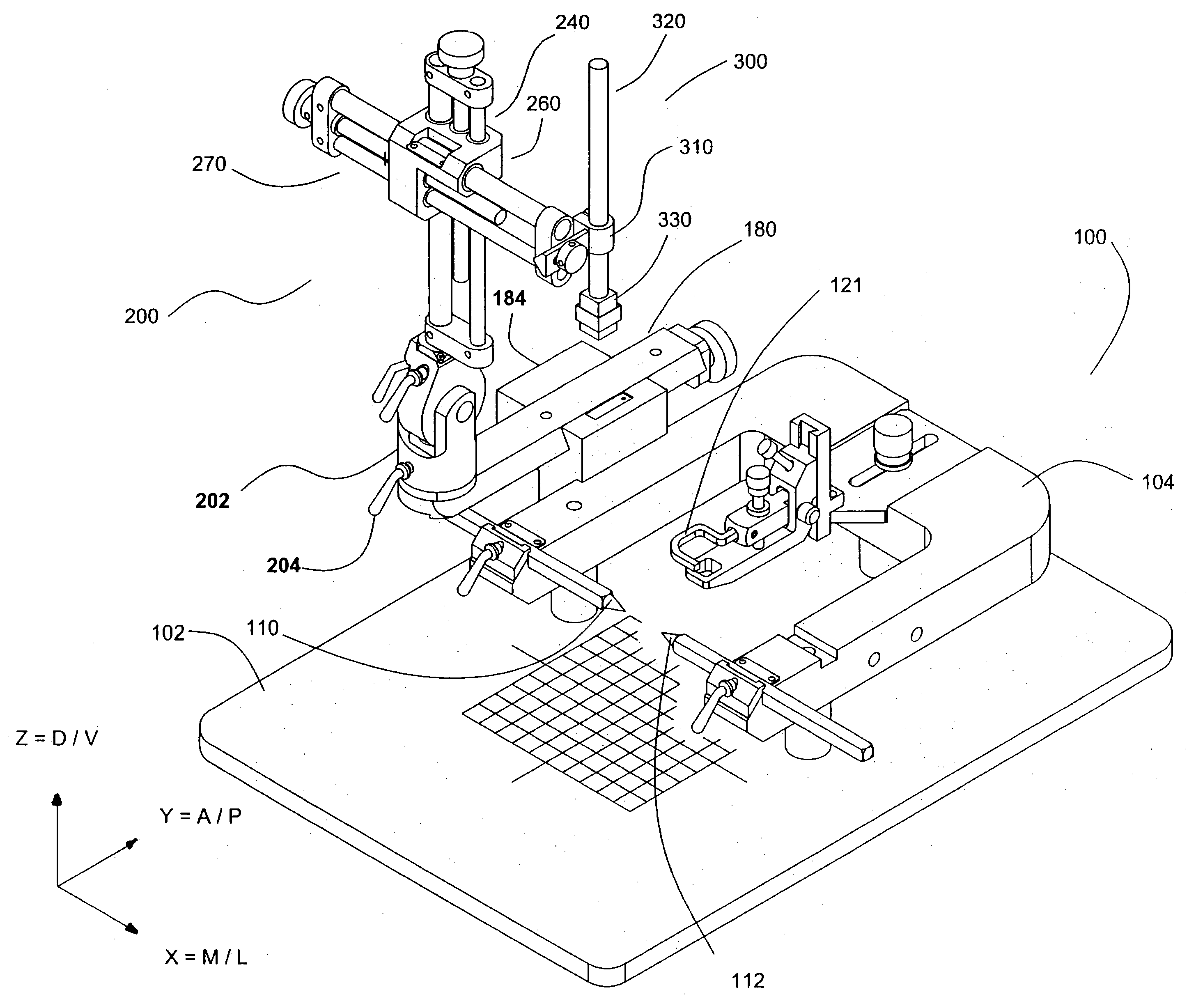
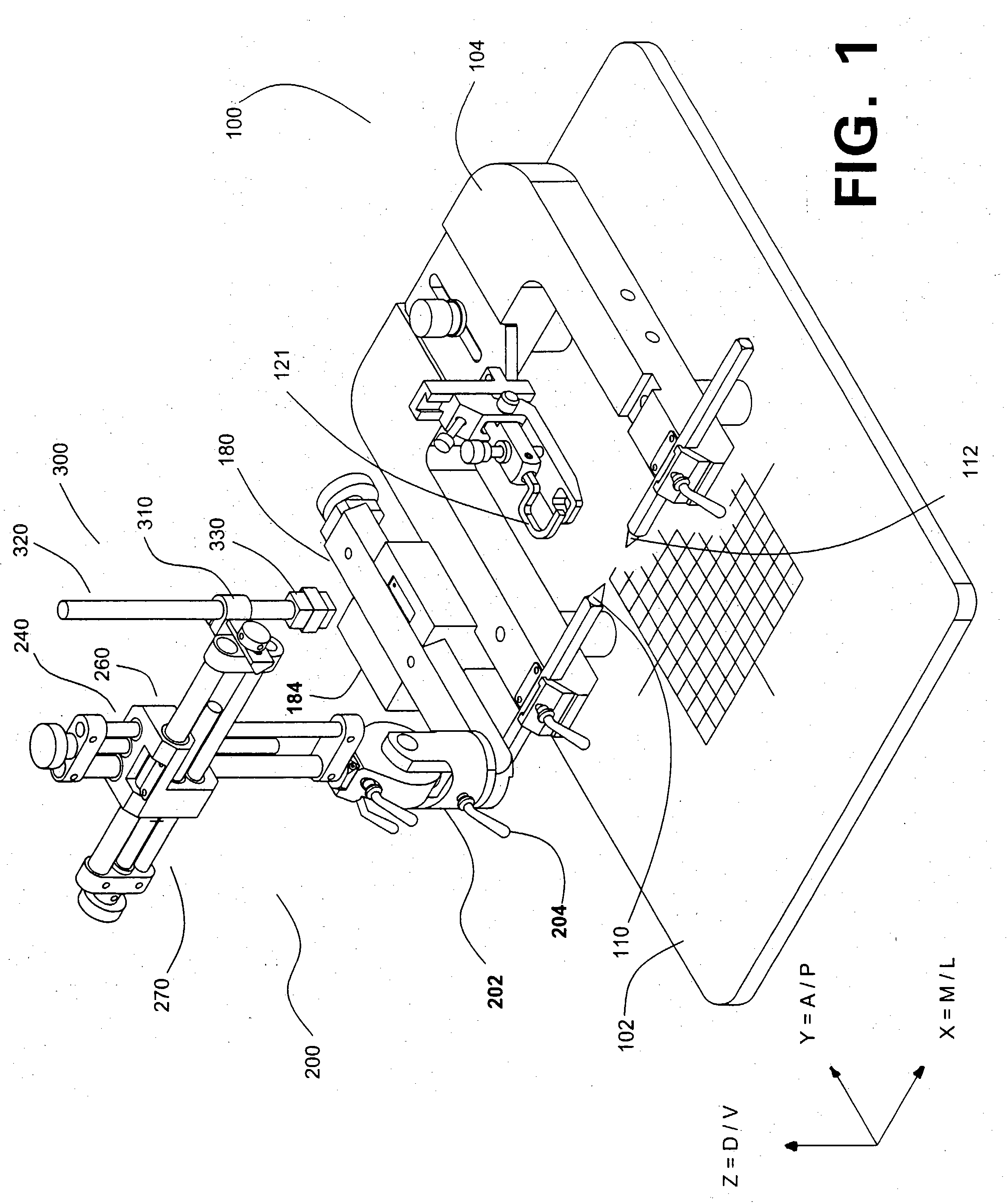
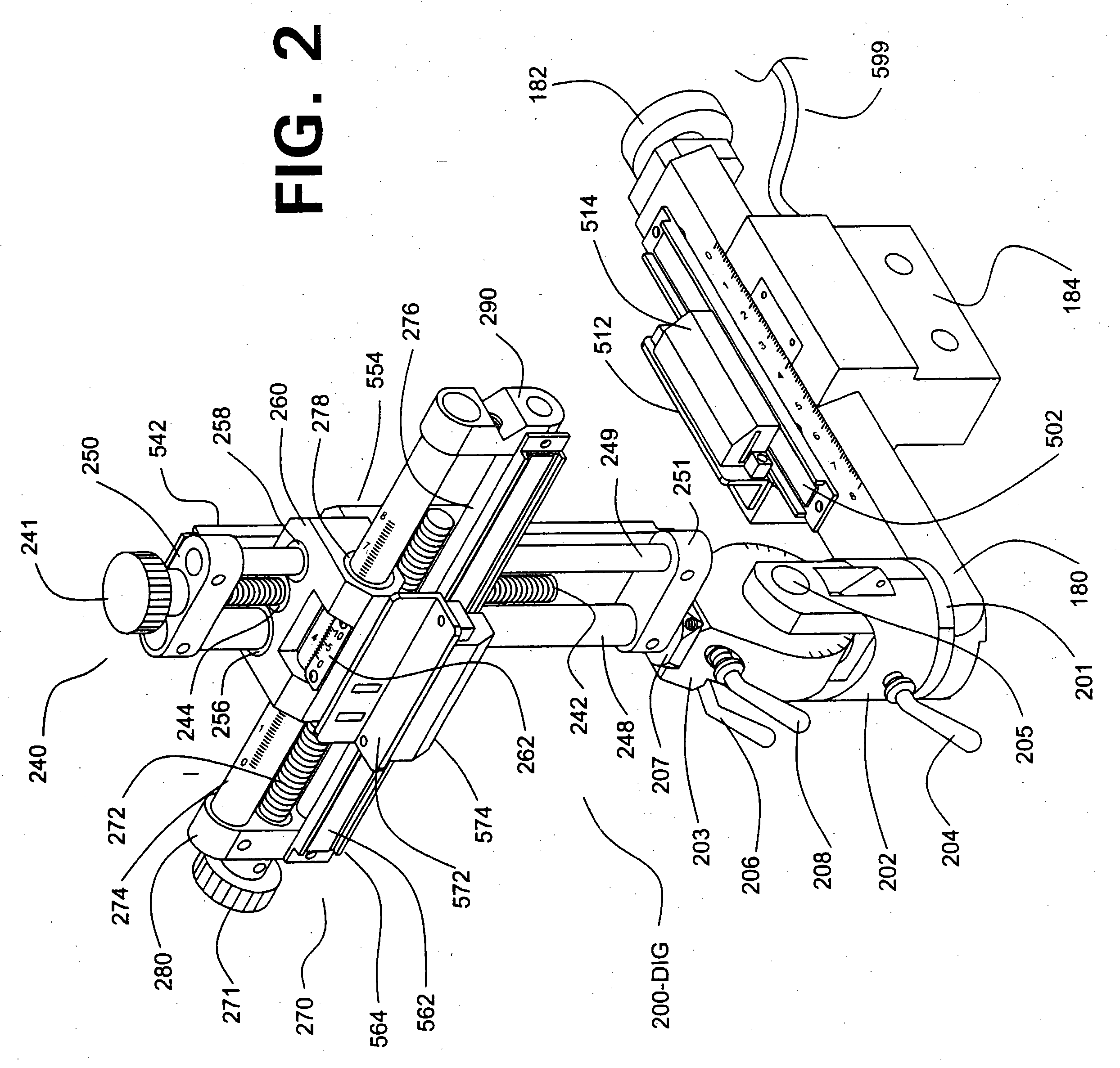
However, when a second-generation system is used, any manual rotation of turret base 202, after a bregma reading has been taken, will render exact repositioning of the manipulator 200 impossible, despite the existence of etched alignment marks on turret base 202 and slide 180.
That is a useful option; however, it does not allow any accurate orthogonal measurements to be made, while the manipulator is in a rotated position.
Although this system allows a second-generation system to be secured in a reliable and true vertical direction, any other angling of the manipulator system, using horizontal axis 205, will render the resulting measurements inaccurate and “pseudo-orthogonal”.
Those measurements and calculations were cumbersome, awkward, and time-consuming, especially if a test was being carried out on a crowded workbench or under a hood, and they often caused errors in measurements.
Although those devices provided a major advance over stereotaxic holders having vernier scales, they suffered from several limitations and drawbacks, including their size and expense.

Method used


Image

  • Digital stereotaxic manipulator with controlled angular displacement and fine-drive mechanism
  • Digital stereotaxic manipulator with controlled angular displacement and fine-drive mechanism
  • Digital stereotaxic manipulator with controlled angular displacement and fine-drive mechanism

Examples


Embodiment Construction

[0077] Referring to the drawings, FIG. 3 (assembled view), FIG. 4 (exploded view, lower half) and FIG. 5 (exploded view, upper half) depict a “third-generation” digital-readout manipulator system 3000, which can be retrofitted to a conventional stereotaxic holder base and U-frame, as shown in FIG. 1, that previously allowed only manual (vernier) readouts.

[0078] This third-generation digital manipulator uses electronic reader heads, to generate electronic signals that will be interpreted and displayed as digital orthogonal location data for an instrument tip, in the same manner as the 'second-generation” systems described above and in application Ser. No. 10 / 036,231, and illustrated in FIG. 2. Those reader heads, as shown in FIG. 2, are shown by callout numbers 514 (for the A / P axis), 554 (for the D / V axis), and 574 (for the M / L axis). Each reader head is mounted adjacent to a linear scaling devices, shown by callout numbers 502, 542, and 562, respectively, in a manner such that ope...


PUM


Abstract

A digital stereotaxic manipulator for animal research is provided with two enhancements. In one enhancement, rotary encoders are provided, to allow tilting of the manipulator, about vertical and / or horizontal axes, to be measured within a fraction of a degree. With assistance from software that applies sine and cosine values, orthogonal coordinates that are emitted by linear reader heads can be corrected to provide accurate orthogonal coordinates, even when an instrument has been rotated and / or tilted substantially. In a second enhancement, a “fine-drive” mechanism provides precise control over dorsal / ventral motion of an instrument. A radial gear is mounted on the main threaded shaft in the vertical arm assembly. A helical gear on a horizontal shaft is used to drive rotation of the radial gear and vertical shaft. If a 1:20 gearing ratio is provided by the helical and radial gears, this provides an operator with 20-times more precise control over vertical motion of an instrument. A detente is also provided, to enable the helical gear to pop out of position without damage, if an operator rotates the main vertical shaft before disengaging the fine-drive mechanism. A digital display device with touch-screen controls is also disclosed.

Description

BACKGROUND OF THE INVENTION [0001] This invention relates to equipment used in biological and medical research that uses small animals, such as rats or mice. [0002] Numerous types of biological and medical research require that the head and / or spine of a rat, mouse, or other small animal must be held in a secure and stationary position throughout the duration of a surgical, drug injection, or similar procedure. One major category of such research, which is discussed throughout this text as an example but which is not intended to be limiting, involves invasive neurological procedures carried out on rats or mice, which are widely used in neurology research because of several factors (including low cost, ease of breeding and care, and the ready availability of extensive information on the gene sequences of both species). For convenience, the discussion below refers to rats as an exemplary species, but it should be understood that these comments and teachings also apply to other types o...

Claims


Application Information

Patent Timeline
IPC IPC(8): A61B19/00
CPCA61B19/201A61D3/00A61B19/203A61B90/11A61B90/14
Inventor SCOUTEN, CHARLES W.UNNERSTALL, JAMES G.THOMPSON, JOHN M.
Owner SCOUTEN CHARLES W
Learn More