Endoluminal prosthesis

a prosthesis and endoluminal technology, applied in the field of tubular prosthesis, can solve the problems of reducing device flexibility, high mortality rate, complex surgical procedure, etc., and achieve the effects of improving device flexibility, small pre-deployment area, and reducing mortality ra

Active Publication Date: 2007-03-08
MEDTRONIC VASCULAR INC
View PDF10 Cites 98 Cited by
  • Summary
  • Abstract
  • Description
  • Claims
  • Application Information

AI Technical Summary

Benefits of technology

[0010] An embodiment according to the present invention provides an improved endoluminal prosthesis having a tubular graft and a support structure attached to the tubular graft and configured in a manner that provides columnar strength while providing improved device flexibility, and a maintaining a relatively small pre-deployed, collapsed profile.
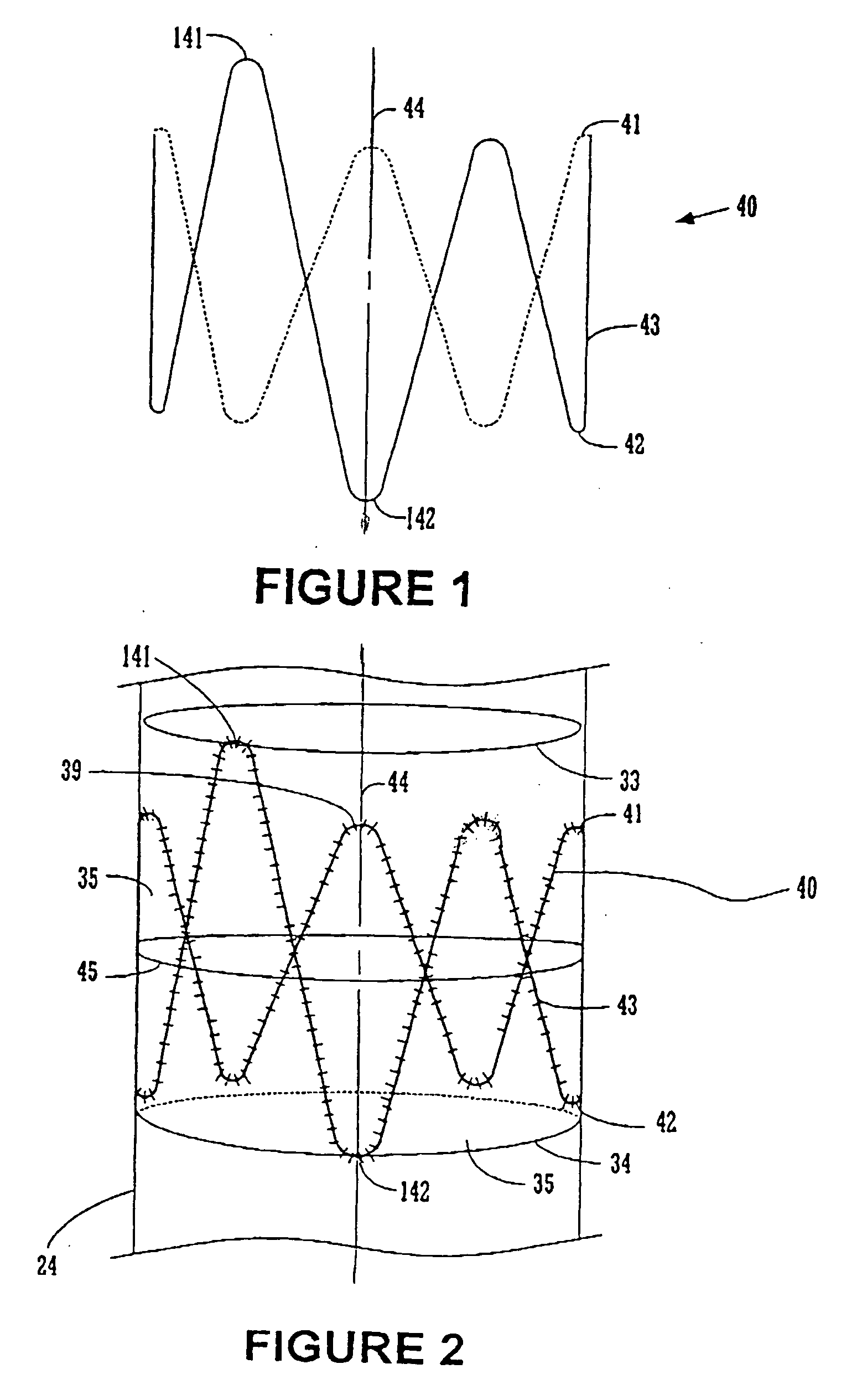
[0012] The annular support members each comprise an annular expandable member formed by an undulating or sinusoidal patterned wire ring. The pattern is formed by a plurality of straight spokes connected by a plurality of apices (alternating crests and troughs) to form a closed ring with an axis extending longitudinally therethrough. Preferably the annular support members are radially compressible springs biased in a radially outward direction, which when released, bias the prosthesis into conforming fixed engagement with an interior surface of the vessel. Annular springs are provided particularly where the annular support member is used to create a seal between the prosthesis and the inner wall of a body lumen. The annular springs are preferably constructed of Nitinol. Examples of such spring means construction are described, for example, in U.S. Pat. Nos. 5,713,917 and 5,824,041 incorporated herein by reference. When used in an aneurysm exclusion device, the spring has sufficient radial spring force and flexibility to conformingly engage the prosthesis with the body lumen inner wall, to avoid excessive leakage, and prevent pressurization of the aneurysm, i.e., to provide a leak resistant seal. Although some leakage of blood or other body fluid may occur into the aneurysm isolated by the prosthesis, an optimal seal will reduce the chances of aneurysm pressurization and resulting rupture.
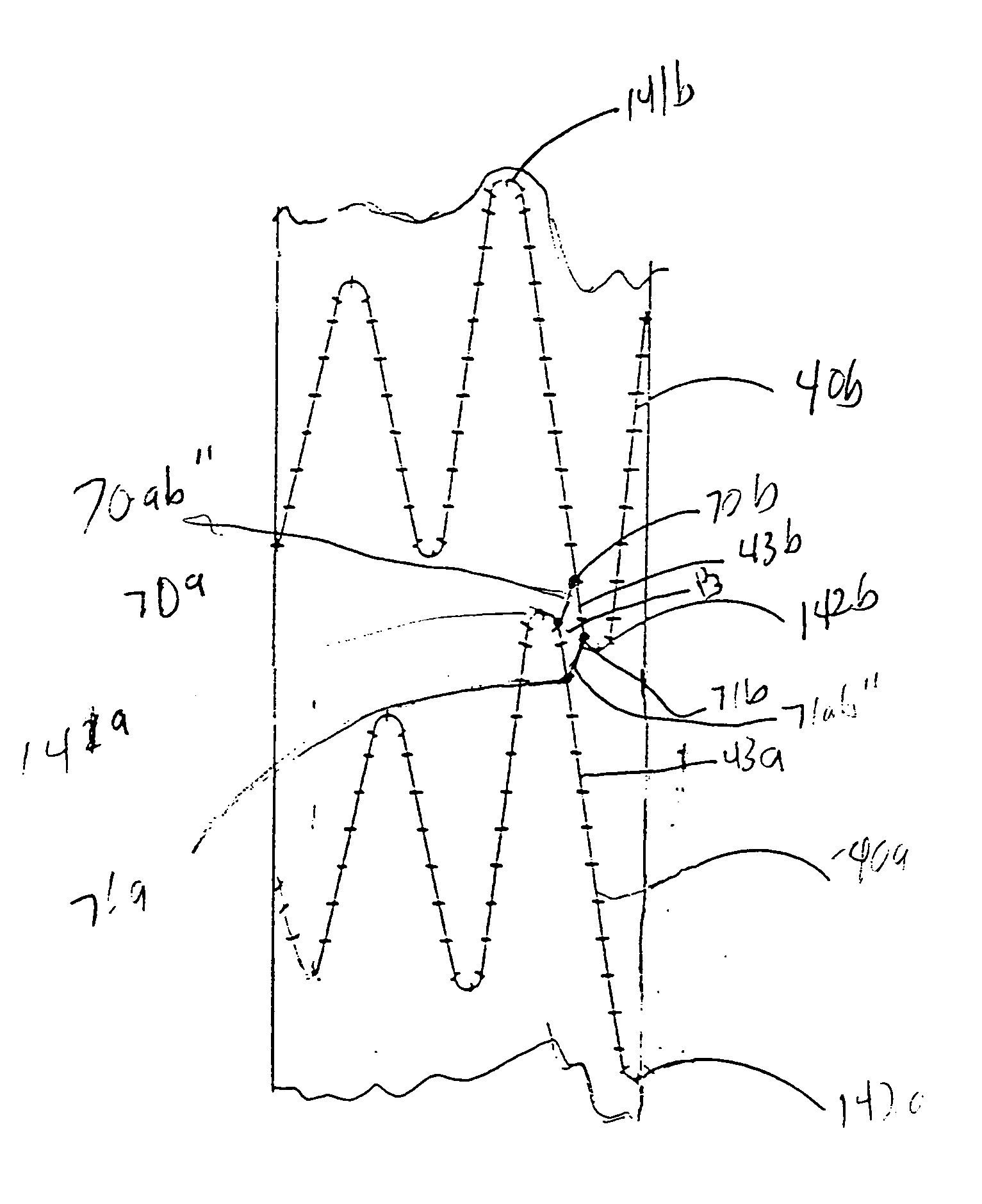
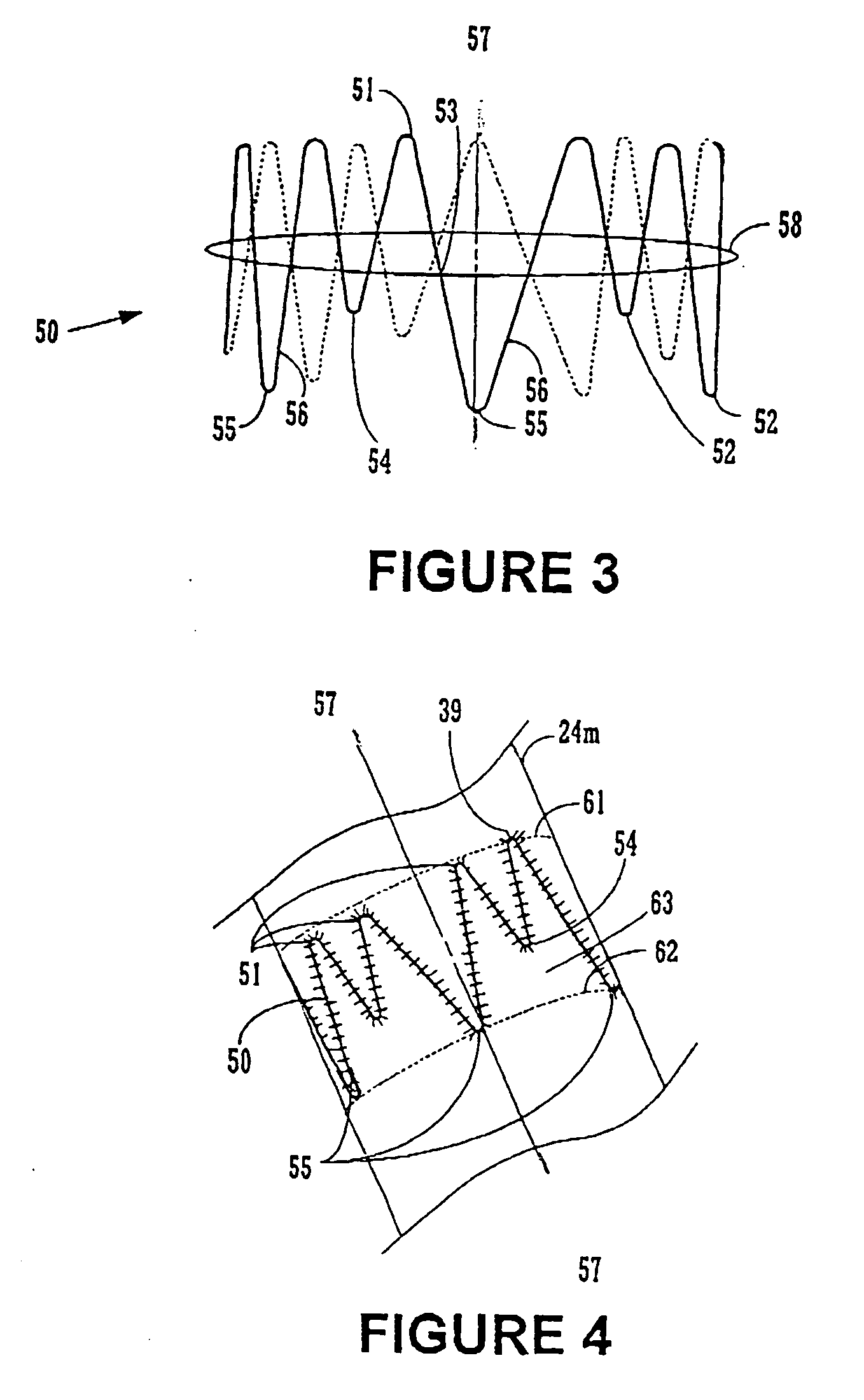
[0013] The annular support members are attached or mechanically coupled to the graft material along the tubular graft by attaching overlapping adjacent apices of adjacent support members within the circumferential areas defined by the support member. The support member may be attached to the graft by various means, such as, for example, by stitching onto either the inside or outside of the tubular graft. Each of the support members defines a corresponding circumferential area of graft material around it. In one embodiment, at least one of the apices of an annular support member is mechanically coupled to the circumferential graft area of an adjacent annular support member. In an embodiment according to the invention, at least one of the apices of the annular support member of the invention extends axially beyond the other apices of that annular support member. In this embodiment, the longer crest(s) and / or trough(s) extend into and are attached to the circumferential graft area of an adjacent annular member. The overlap on the graft thus provides columnar strength along the length of the graft from one support structure through the graft and to the next support structure. The overlapping structure also prevents collapse of the graft between support structures. Further, providing fewer overlapping structures allows greater radial compressibility of the prosthesis.
[0014] In one embodiment according to the invention, the apices, or crests and troughs of at least one support structure overlap lengthwise (i.e., with respect to the length or axis of the prosthesis) an apex of an adjacent support structure. Such an apex is offset from adjacent apices of the adjacent support structure about the circumferential area of the adjacent support structure. The troughs of a support structure are staggered about the circumference from the crests of an adjacent support structure so that the support structures do not physically touch. In one embodiment, longer crests or longer troughs of each of the support members are substantially aligned with the other longer crests or longer troughs of adjacent support structures, respectively, to provide column strength along a desired length of the prosthesis.
[0017] The present invention in the embodiment of an Abdominal Aortic Aneurysm (“AAA”) device, the prosthesis is able withstand the loads applied during deployment and the cyclical loading in the body for a reasonable duration and provides sealing attachment of the annular support structure to the inner wall of the body lumen.
[0019] The endoluminal prosthesis may be in the form of either a straight single-limb tubular member or a generally Y-shaped bifurcated tubular member having a trunk joining at a graft junction with a pair of lateral limbs, namely an ipsilateral limb and a contralateral limb. In a bifurcated prosthesis, the proximal portion of the prosthesis comprises a trunk with a proximal opening and the distal portion is branched into at least two branches with distal openings. Thus body fluids may flow from the proximal opening through the distal openings of the branches. Preferably the ipsilateral limb is longer so that when deployed, it extends into the common iliac. A single limb extension member is provided having a mating portion for engaging and sealing with a lateral limb of a bifurcated member and a leg (whose length may vary as selected to mate with a particular patient's anatomy) extending coaxially from a distal end of the mating portion. In one embodiment according to the invention, the improved annular support members are located on the proximal portion of the prosthesis. In another embodiment according to the invention, the annular support members are located on at least one of the iliac portions to provide increased flexibility when deployed in a tortuous vessel.

Problems solved by technology

The surgical procedure is complex and requires long hospital stays due to serious complications and long recovery times and has high mortality rates.
Although frequently referred to as stent-grafts, these devices differ from covered stents in that they are not used to mechanically prop open natural blood vessels.
However, the features that provide columnar strength may also reduce device flexibility that permits sealing placement of the device within a tortuous vessel, such as, e.g., a diseased iliac vessel.
Further, the devices are subject to cyclical loading and other stresses.

Method used


Image

  • Endoluminal prosthesis
  • Endoluminal prosthesis
  • Endoluminal prosthesis

Examples


Embodiment Construction

[0036]FIGS. 1-8B illustrate various embodiments of the support structures and endoluminal prostheses according to the present invention. Although an endoluminal prosthesis according to the invention may be used in any body lumen that conducts body fluid, it is described herein with reference to treatment of an aortic aneurysm, in particular in the abdomen of a patient.

[0037]FIG. 1 illustrates a first embodiment of an annular support member 40 used in an endoluminal prosthesis of an embodiment according to the invention. The annular member 40 comprises five connected V-shaped patterns in a cylindrical undulating ring (undulating member or straight spokes coupled at apices). In forming this pattern, the annular member 40 comprises straight spokes 43 connected by rounded alternating crests 41 and troughs 42 encircling a central axis 44 to provide a continuous ring. Of the crests 41 and troughs 42 there is at least one longer crest 141 and at least one adjacent longer trough 142, each ...


PUM


Abstract

An endoluminal prosthesis is provided that includes a tubular graft and an expandable annular support structure for use in a body lumen through which body fluids flow. The annular support structure is coupled to the tubular graft where it is to be sealingly engaged with the inner wall of a body lumen so that the graft and support structure, in combination, provide an improved seal. An embodiment according to the invention provides an annular structure with longitudinally staggered apices providing multiple levels of contact with the inner body lumen wall to provide a seal at multiple levels along the length of the prosthesis. One embodiment relates to tubular grafts for endoluminal placement within blood vessels for the treatment of abdominal and other aneurysms.

Description

FIELD OF THE INVENTION [0001] The present invention relates to tubular prostheses such as grafts and endoluminal prostheses including, for example, stent-grafts and aneurysm exclusion devices, and methods for placement of such grafts and endoluminal structures. More particularly, the present invention relates to an improved a tubular graft and support structure for placement within or in place of a body lumen. BACKGROUND OF THE INVENTION [0002] A wide range of medical treatments have been previously developed using “endoluminal prostheses,” which terms are herein intended to mean medical devices which are adapted for temporary or permanent implantation within a body lumen, including both naturally occurring or artificially made lumens. Examples of lumens in which endoluminal prostheses may be implanted include, without limitation: arteries such as those located within coronary, mesentery, peripheral, or cerebral vasculature; veins; gastrointestinal tract; biliary tract; urethra; tra...

Claims


Application Information

Patent Timeline
Patent Type & Authority Applications(United States)
IPC IPC(8): A61F2/86A61F2/06A61F2/82
CPCA61F2/07A61F2002/065A61F2/89A61F2002/826A61F2002/075
Inventor ARBEFEUILLE, SAMUEL
Owner MEDTRONIC VASCULAR INC
Why Eureka
Try Eureka