Calibration of 3D field sensors

a 3d field sensor and sensor technology, applied in the field of sensors, can solve the problems of difficult magnetometers, long process, and rarely valid assumptions

Active Publication Date: 2007-03-08
NOKIA TECHNOLOGLES OY
View PDF7 Cites 80 Cited by
  • Summary
  • Abstract
  • Description
  • Claims
  • Application Information

AI Technical Summary

Problems solved by technology

In practice, however, these assumptions are rarely valid.
Magnetometers are especially tricky, because external magnetic components attached to a device in which the magnetometer resides can result in scale and offset errors and can also effectively introduce linear dependence among the measuring axes.
Usually this process is lengthy and generally involves complicated steps for the user.
This process also gives the offset, but cannot find possible linear dependence among different axes.
To find possible linear dependence among different axes, it is usually required to indicate certain reference directions, which is also time consuming for the user.
Unfortunately, 3D magnetometers are relatively new, and most calibration methods are for 2D sensors.
This process still takes user input regarding known headings and is typically impractical for 3D field sensors.

Method used


Image

  • Calibration of 3D field sensors
  • Calibration of 3D field sensors
  • Calibration of 3D field sensors

Examples


Embodiment Construction

[0021] For ease of reference, the present disclosure is divided into a number of different sections.

[0022] 1. Introduction

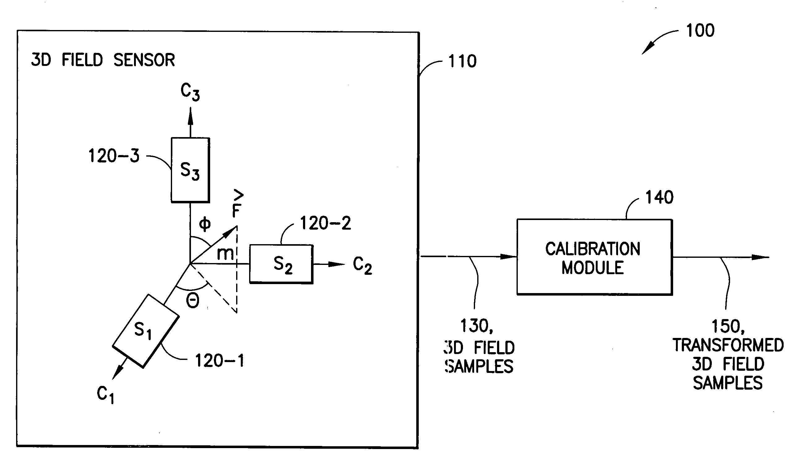
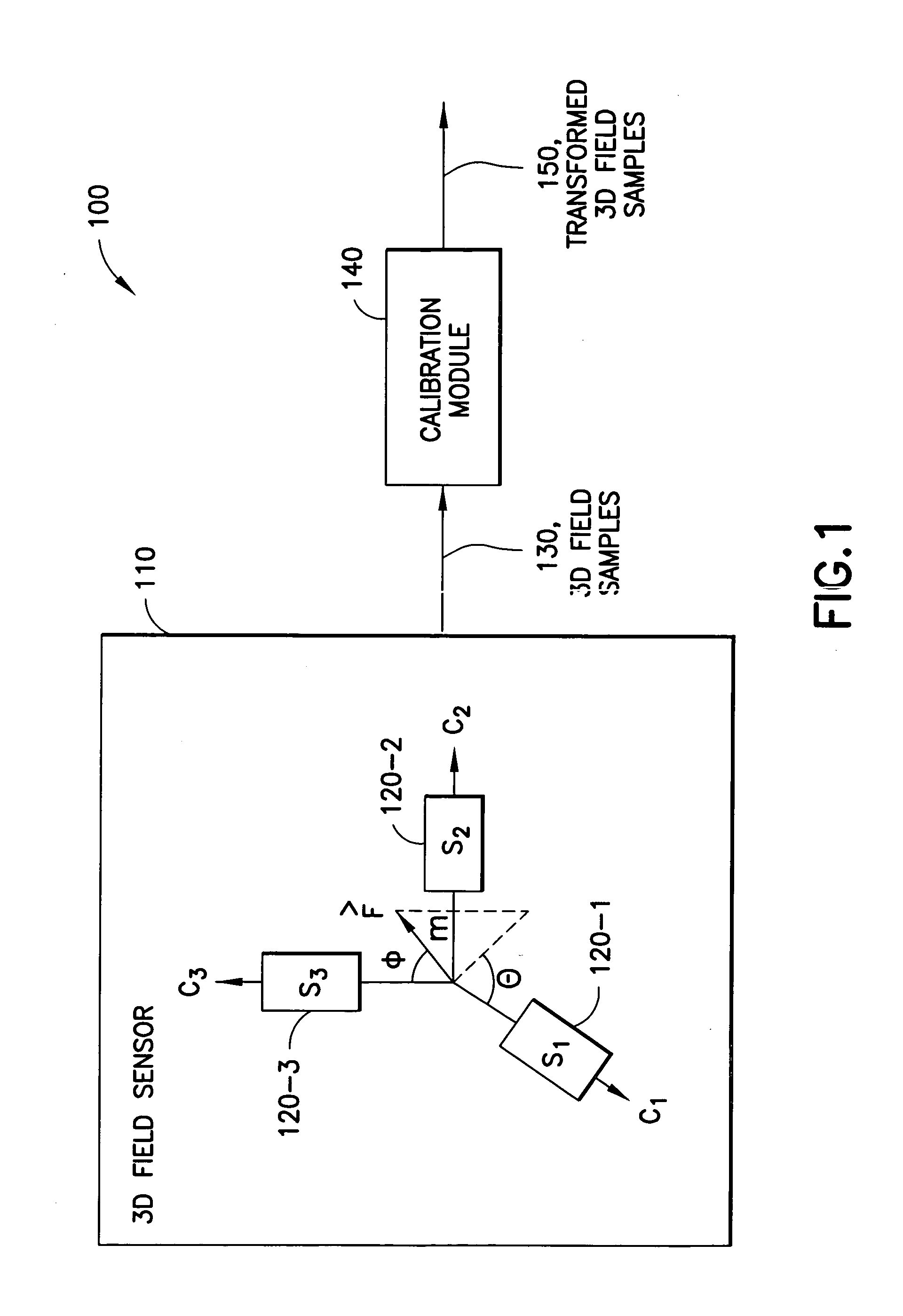
[0023] The present disclosure is primarily directed to calibrations of 3D field sensors such as three-axis magnetometers (TAM), but in principle the techniques herein can be applied to any three-axis sensor that is used to sense a linear field. Examples of such sensors could be a three-axis accelerometer sensing the earth's gravity or a sensor sensing an electric field in three dimensions.

[0024] Of course, there is any number of straightforward ways of calibrating such a sensor with some kind of reference signal(s). Our setting, however, is different. A TAM can be used in conjunction with a three-axis accelerometer to obtain the orientation of the device in reference to the coordinate system set by the earth's gravitational and magnetic fields. In astronautical sciences, this is usually called the attitude of the spacecraft. We, however, are interested in the ...


PUM


Abstract

An apparatus-based method is disclosed for calibration of a 3D field sensor. The method includes accessing a plurality of samples, where the samples are from the 3D field sensor. Each sample represents a magnitude and an orientation of a three-dimensional field sensed by the 3D field sensor. Using the plurality of samples, a plurality of parameters is determined of an ellipsoid. The determination of the plurality of parameters is performed so that the ellipsoid fits the plurality of samples. A transformation is determined that transforms the ellipsoid into a sphere. The transformation is applied to a sample to create a transformed sample. Apparatus and signal bearing media are also disclosed.

Description

CROSS-REFERENCE TO RELATED APPLICATIONS [0001] This application is a continuation in part of U.S. patent application Ser. No. 11 / 219,576, filed on Sep. 2, 2005, which is herein incorporated by reference.TECHNICAL FIELD [0002] This invention relates generally to sensors that measure three-dimensional (3D) fields and, more specifically, relates to calibration of such sensors. BACKGROUND OF THE INVENTION [0003] A 3D field sensor is a sensor that measures direction and magnitude of some field in three-dimensional (3D) space. For example three orthogonal magnetometer elements can measure the direction and magnitude of the surrounding magnetic field. Similarly, three orthogonal accelerometer elements can sense the direction and magnitude of acceleration or more importantly the gravitational field, which is typically indistinguishable from acceleration. [0004] As already suggested above, in almost all cases, a 3D field sensor includes at some level three single-dimensional sensors oriented...

Claims


Application Information

Patent Timeline
Patent Type & Authority Applications(United States)
IPC IPC(8): G01C17/38
CPCG01C17/38G01C25/00G01R33/0206G01P21/00G01P15/18
Inventor PYLVANAINEN, TIMO PEKKA
Owner NOKIA TECHNOLOGLES OY
Why Eureka
Try Eureka