Slotted metal truss and joist with supplemental flanges

a technology of supplemental flanges and metal trusses, which is applied in the direction of joists, girders, walls, etc., can solve the problems of buckling (euler or local) probably the most common and most catastrophic, failure becomes catastrophic, and the structure may fail to support a load, so as to improve the resistance to local shear deflection of beams, good conductors, and enhanced structural effects

Active Publication Date: 2007-03-15
LIGHT GAUGE STEEL AMERICA
View PDF57 Cites 75 Cited by
  • Summary
  • Abstract
  • Description
  • Claims
  • Application Information

AI Technical Summary

Benefits of technology

[0011] These supplemental flanges are formed by stamping out a flange in the web on three flange sides and then bending the supplemental flange away from the web on the fourth, uncut side, forming a slot in the web. The result then is a supplemental flange extending from the web at the slot edges. Typically, the supplemental flange usually extends normal to the web and parallel to the primary flanges extending from the web edges, although it can be angled from the web other than normal. The slot in the beam web presents a reduced web area through which heat or sound may be conducted.
[0013] Rather than weaken the beam at the slot, the beam is in fact strengthened through a few mechanisms. First, the longitudinal extent of the web of a traditional beam presents a large vertical plane susceptible to local shear buckling under load that can lead to Euler bucking. Introducing slots having supplemental flanges into the web reduces that extent. That is, the Supplemental Flange Beam (“SFB”) itself actually stiffens the web plane by creating smaller flat planes in the web plane than are present in standard steel studs thus increasing local shear buckling resistance.
[0014] The calculation discloses that for vertical loading the SFB provides better stability in buckling resistance due to the center of gravity being moved away from the plane of the web toward the opening of the channel section. This effect distributes the vertical load more uniformly over the SFB cross-sectional area; rather than mostly in the web as standard steel studs do; and thus forcing local buckling effects to require a higher vertical loading than standard steel studs can handle. The SFB also enhances resistance to Euler buckling (long column lateral deflection) by the new properties the supplemental flanges provide. In short, for the beam to bend at the slot, both the supplemental and primary flanges orthogonal to the web must also bend, but with the supplemental flanges, there is increased resistance to that bending.
[0015] The supplemental flange can be either continuous (fully encompassing the slot) or discontinuous (not completely encompassing the slot) although the former will provide for greater strength and structural stability than the latter. When all the original material in a traditional metal stud, or other beam, remains in the final SFB product, in the case of supplemental flanges extending from the full length of slot sides the SFB retains more than the total cross-sectional area of the traditional stud, which retains its support for compressive loads and provides additional rigidity that equates to better stability than traditional steel studs (other comparable beams). This is demonstrated in both the x-axis and y-axis bending calculations below.
[0026] It has also been determined that resistance to local shear deflection of the beam is also enhanced for the slotted beam with supplemental flanges extending from the web at slot sides. That is, the beam with supplemental flanges also supports a greater lateral load, or a load placed intermediate a nonvertical beam directly on the web, on a slotted metal beam with supplemental flanges than on a metal beam without these features.
[0027] Though the beam is structurally enhanced by the supplemental flanges as discussed above, perhaps the most advantageous contribution of the supplemental flanges is that the web can be slotted without diminishing the structural integrity of the beam, and in fact providing an enhanced structure. The slots interrupt heat (and acoustical) flow through the web across the wall employing the beam. Prior to the described slotted beam with supplemental flanges, metal beams were disfavored because they are a poor insulator; in fact, they are a good conductor, defeating efforts for energy conservation and noise containment. Wood remained the preferred material because of the low conductivity of wood. For example, the “R” factor for wood (fir, pine, and spruce) for a 2″×6″ stud is 361 K / w. [1 W / mK=0.578 BTU / Hr−ft−° F.]. The “R” factor for a steel same-sized slotted stud is 846 K / W. The rate of heat loss through the wood stud is 0.055 W and through the slotted steel stud is 0.024 K / W, or less than half. The steel stud immediately becomes competitive and even advantageous. In addition, instead of air in the slot, which conveys heat by convection, insulation can be added. The slotted beam enhanced structurally by the supplemental flanges and thermally by the slots and insulation in the slots thus becomes an attractive wall construction alternative. It is clear that the open slot left in the SFB that is created by the supplemental flange manufacturing process can vary in width and length depending on the requirements needed from the SFB. Changes in this width and length will affect the various geometric properties

Problems solved by technology

Of all modes of failure, buckling (Euler or local) is probably the most common and most catastrophic.
That is, a structure may fail to support a load when a member in compression buckles, that is, moves laterally and shortens in length.
This means that any buckling encourages further buckling and such failure becomes catastrophic.
Such beams are very poor energy conservers.
Also, such slots may receive insulation that further impede conductivity.
Similarly, a steel beam is a good acoustic conductor, which is detrimental in many applications.
As in thermal conductivity, re-shaping of a significant portion of the web or the flanges will reduce the acoustic conductivity of the beam and therefore the wall.
First, the longitudinal extent of the web of a traditional beam presents a large vertical plane susceptible to local shear buckling under load that can lead to Euler bucking.
Prior to the described slotted beam with supplemental flanges, metal beams were disfavored because they are a poor insulator; in fact, they are a good conductor, defeating efforts for energy conservation and noise containment.

Method used


Image

  • Slotted metal truss and joist with supplemental flanges
  • Slotted metal truss and joist with supplemental flanges
  • Slotted metal truss and joist with supplemental flanges

Examples


Embodiment Construction

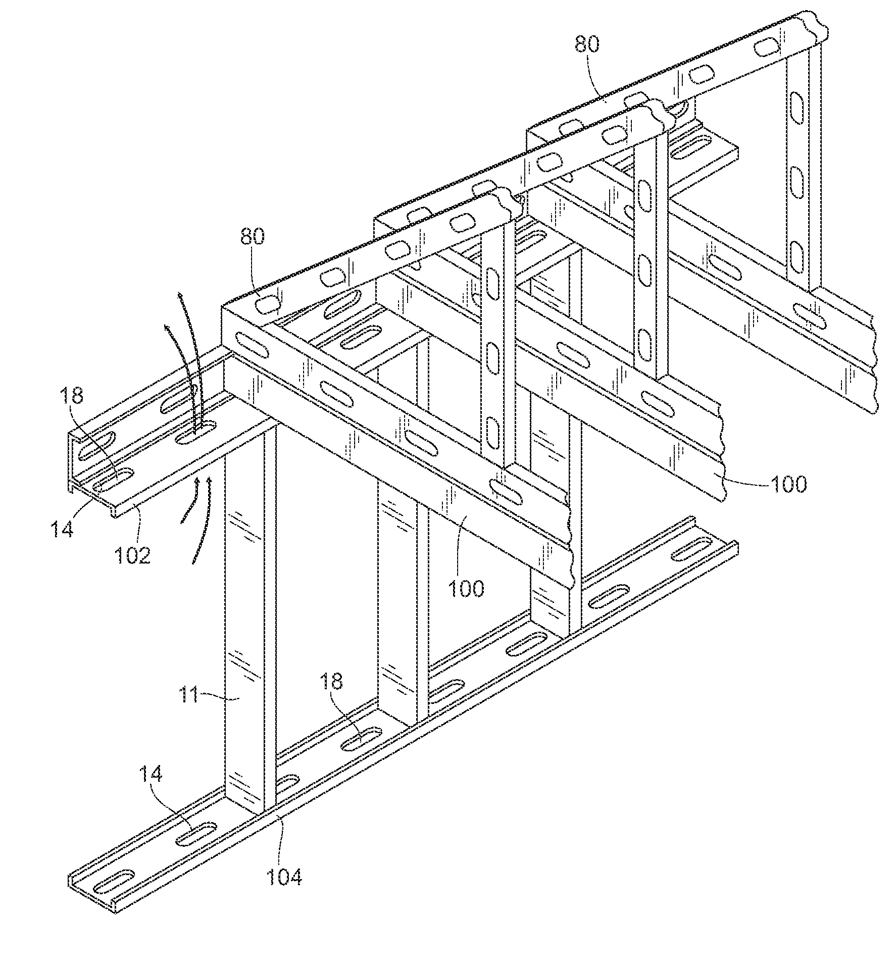
[0046] The slotted metal beam 10 is intended for use in conventional building construction, such as a stud in a wall, building joists and trusses. In the conventional manner of wall and building construction, a plurality of studs is spaced apart vertically in parallel between horizontal floor joists and ceiling joists 100. Typically, a channel stud header 102 connected to the ceiling joists 100 and opening downward receives upper ends 11 of the studs 10. Similarly, a channel stud footer 104 connected to the floor joists 100 and opening upward receives lower stud ends 13. Because the joists 100 are required to support a lateral, or transverse load, they may be larger and stronger than the studs 10, which support a compressive, or longitudinal load.

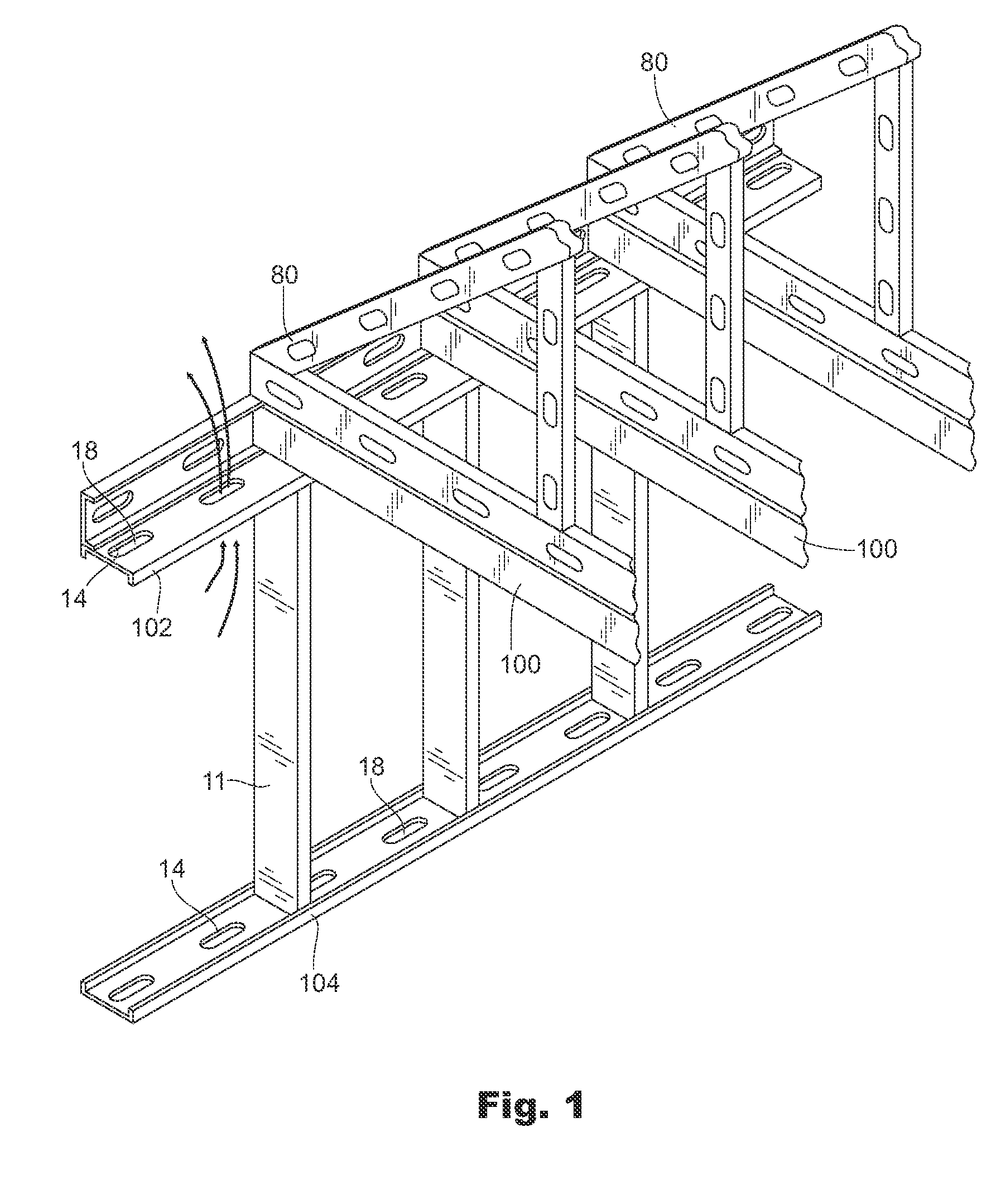
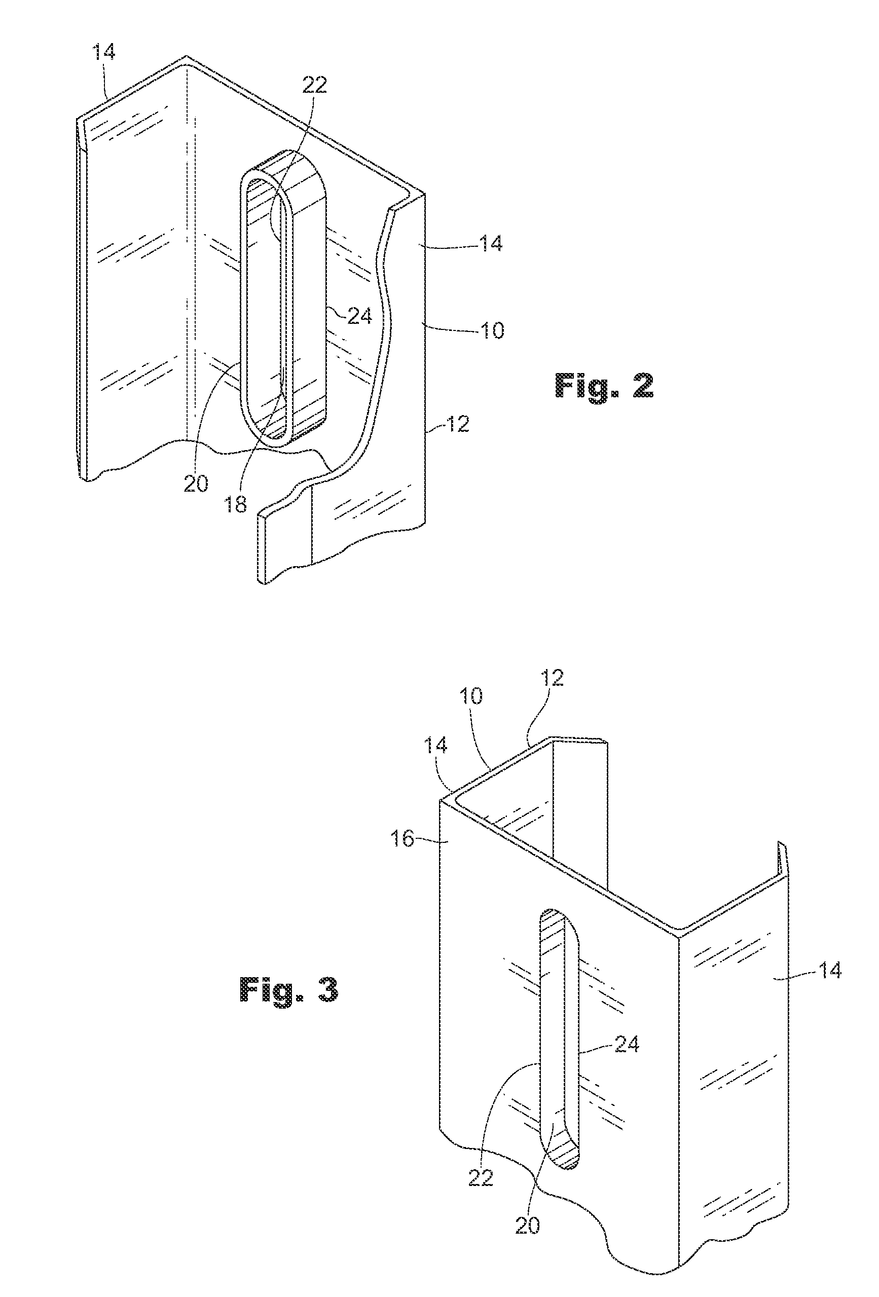
[0047] The beam 10 comprises a conventional C-shaped channel 12 including a pair of parallel primary flanges 14 extending a same extent orthogonally from and separated by a web 16. In the preferred embodiment, at least one and preferably a...


PUM


Abstract

A slotted channel with a supplemental flange as a building member has at least one supplemental flange extending from at least one slot in the member web or primary flanges yielding a building member with increased strength, both compressive (longitudinally) and in shear (transverse). The slotted member presents a reduced area through which heat or sound may be conducted and slots in which insulation is received, both increasing resistance to heat and sound transfer.

Description

BACKGROUND [0001] 1. Field of the Invention [0002] This invention relates to steel trusses and joists comprising parallel flanges extending orthogonally from web sides, and more particularly to a truss or a joist with at least one slot in the web or primary flanges and including supplemental flanges extending from slot sides. [0003] 2. Prior Art [0004] Interior wall construction using horizontal channel beams as headers and footers and matching vertical studs received into the channel beams is well-known. Commonly, the studs are also channel-shaped and both are made of metal, typically cold formed metal and more typically steel. Similarly, metal buildings employ girts (sidewall bracing) and perlins (roof bracing). Roof rafters, headers, footers, beams, and joists and trusses comprised of a plurality of similar elongate components can also employ channel shaped members. All of these building components have in common that they are elongate and straight, including the truss comprising...

Claims


Application Information

Patent Timeline
Patent Type & Authority Applications(United States)
IPC IPC(8): E04H12/00E04C3/30
CPCE04B1/24E04B2/7412E04B2001/2463E04C2003/0473E04B2001/2484E04C3/07E04B2001/2466
Inventor EDMONDSON, DENNIS
Owner LIGHT GAUGE STEEL AMERICA
Why Eureka
Try Eureka