Arrangement for damping of vibrations and defection in a tool holder

a tool holder and vibration damping technology, applied in the field of vibration damping and apparatus for vibration damping, can solve the problems of vibration and flexion, low possibility of increasing the diameter of the tool holder, and two types of vibrations are particularly problematic, so as to achieve the effect of substantially increasing the energy (force and motion) applied to the tool

Inactive Publication Date: 2007-03-15
TEENESS AS
View PDF31 Cites 18 Cited by
  • Summary
  • Abstract
  • Description
  • Claims
  • Application Information

AI Technical Summary

Benefits of technology

[0021] The present invention utilizes force exchange devices in the form of force applying devices and damping devices. As force applying devices actuators having a flexible fixing device (support) are preferably used, so that the actuators can be moved and the forces applied directly onto the tool holder or via a lever or force transmission sleeve(s). The advantage is the fact that the overhang of the tool and the direction of the force can be changed relative to the cutting forces occurring in the machining process, or it is desirable to apply a force in a distinct desired direction. The invention also permits using tool holders having different shapes and dimensions in the same holder. With the present invention, the energy (force and motion) that is applied to the tool can be substantially increased via shear forces by actuators positioned directly on or recessed in pockets on the tool holder as previously described.

Problems solved by technology

Machining, such as turning, drilling or milling, frequently causes problems of vibrations and flexions, particularly when the length of the non-clamped or canti-lever part of the tool exceeds 4-5 times the diameter.
Vibration problems usually occur in internal cutting, when deep cutting is intended and the possibility of increasing the diameter of the tool holder is low.
Two types of vibrations are particularly problematic; flexional vibrations and torsional vibrations.
These vibrations result in poor productivity, poor surface finish, reduced tool working life, and they often prevent machining.
Because of tool flexion, the intended dimension or the intended shape will not be obtained upon a cutting operation.
Workpieces, particularly workpieces having a thin-walled cross section, are also subject to the same problems of medium flexion and vibrations.
The problem associated with mechanical dampers is i.a. that the heavy materials are expensive, each tool is limited to specific cantilever lengths and that the damper occupies space in the tool holder, thus weakening the tool.
The materials oil and rubber are frequently used and they may be hard to obtain in a stable quality and they change properties with temperature and working life.
In addition, such damping systems have limitations as to how low frequencies may be achieved.
Also, twin mass dampers add an additional mass, hampering the balancing of tools rotating at a higher rpm.
The problem associated with the said locations of actuators is the fact that they do not allow flexibility along the length of the overhang.
Also, the force transmission to the tool will be inefficient since these shear forces have to be very large in order to resist motions farthest out on the tooth tip.

Method used


Image

  • Arrangement for damping of vibrations and defection in a tool holder
  • Arrangement for damping of vibrations and defection in a tool holder
  • Arrangement for damping of vibrations and defection in a tool holder

Examples


examples of embodiments

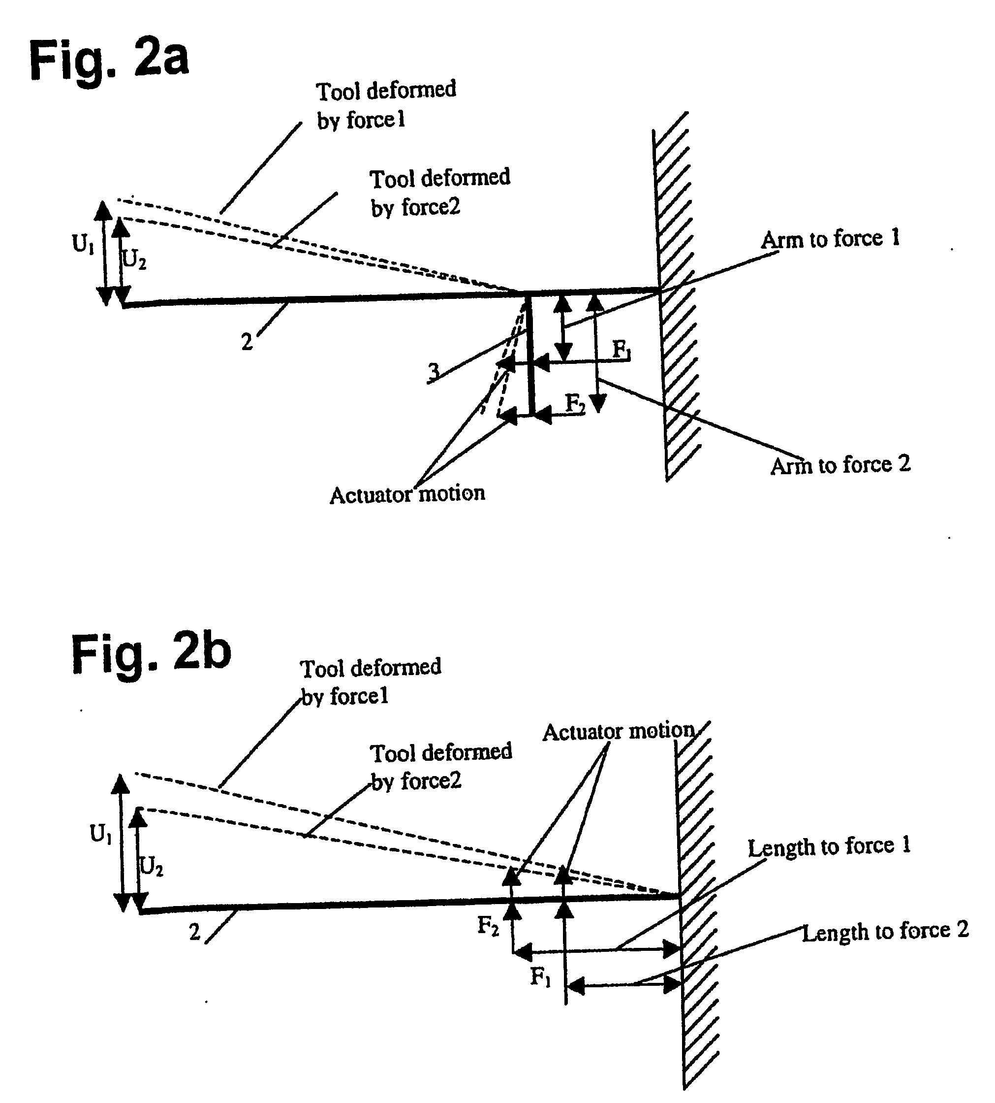
Force Transmission According to the Moment Principle

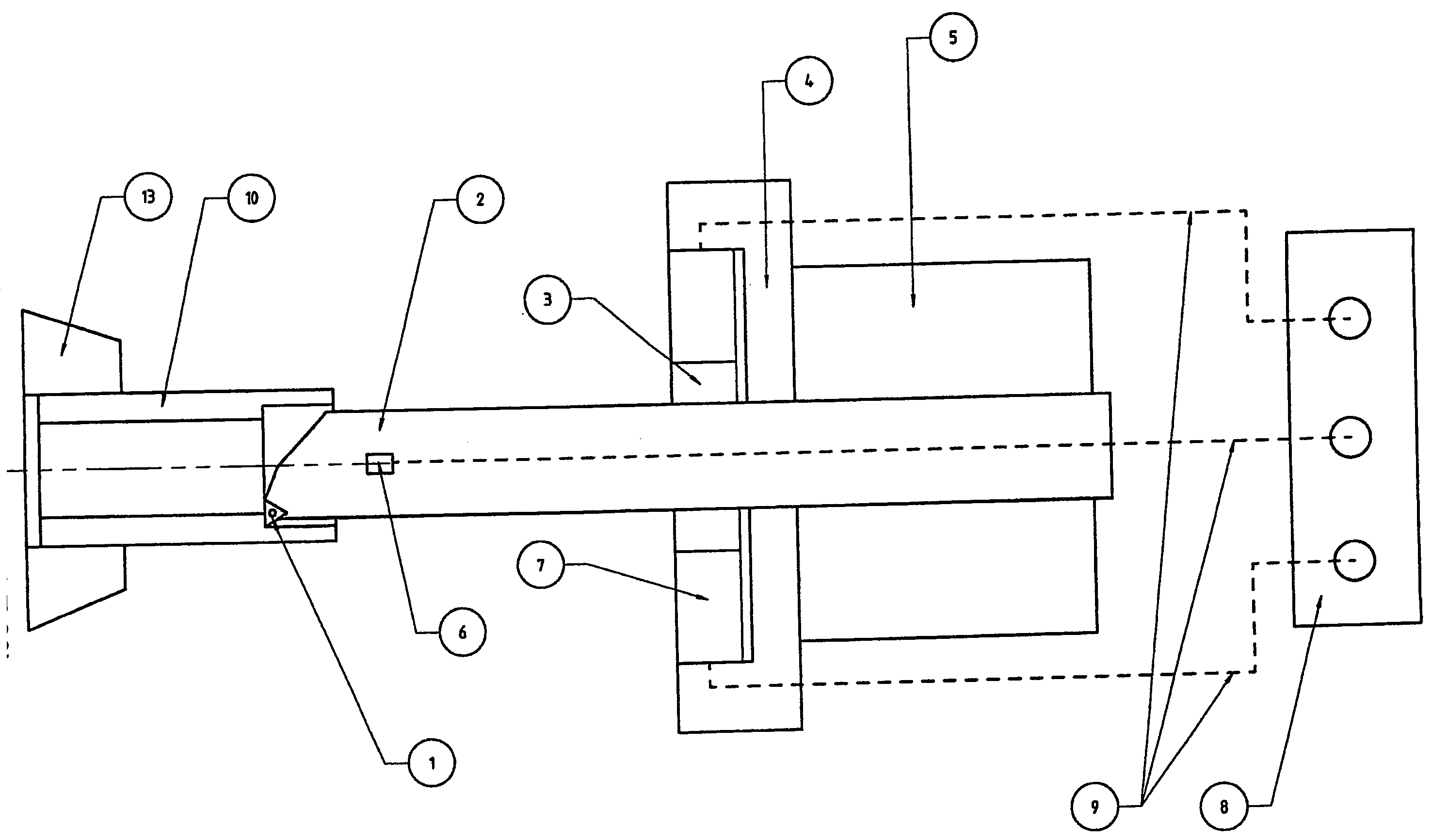
[0050]FIG. 4 shows an embodiment of the damping device according to the invention. A tool holder 2 is placed in a tool clamp 5. A tooth 1 for machining a workpiece 10 is fixed to the tool holder 2. The tool clamp 5 could be modular and adapted to different diameters and geometrical configurations (triangular, oval, square, for example) of the tool holder. Actuators 7 are fixed between the tool clamp 5 or a specific locator sleeve 4 and a lever 14 spaced outwardly from the surface of the tool holder 2. The actuators 7 are fixed to or recessed into the tool clamp 5 on the side facing the tooth 1. Alternatively, the actuators 7 could be fixed to a locator sleeve 4 specific for the actuators. The locator sleeve 4 could be spaced from the tool holder 5, so that the damping device can slide along the bar body. The force from the actuators 7 could act in a manner to deform the tool holder 2 directly, or the tool holder 2 and / or tool cla...


PUM

PropertyMeasurementUnit
forceaaaaaaaaaa
pressureaaaaaaaaaa
dimensionsaaaaaaaaaa

Abstract

The invention relates to a device for damping vibrations and/or controlling the flexion of an object (2, 10) in machining, said device comprising at least one force exchange device (7) which could be a force applying device or a damping device. A such force applying device (7) is for applying a force having a force component directed at right angles to the surface of the object and/or for applying a moment to the object (2, 10). A damping device (7) of this type is for absorbing vibrations from the object (2, 10) and is adapted to absorb a force component directed at right angles to the surface of the object or to absorb a moment from the object.

Description

TECHNICAL FIELD [0001] The present invention relates to a method and an apparatus for vibration damping, and for damping flexing of tools and workpieces in machining. BACKGROUND [0002] Machining, such as turning, drilling or milling, frequently causes problems of vibrations and flexions, particularly when the length of the non-clamped or canti-lever part of the tool exceeds 4-5 times the diameter. [0003] Vibrations and flexions are closely related. When applying the tooth to the workpiece there will first be a medium flexion caused by the cutting force applied to the tooth. When the tool is vibrating, a reciprocating motion will occur above and below the medium flexion (see FIG. 1). This motion will be amplified if the frequencies applied by the cutting force approaches the resonance frequencies of the tool. [0004] Vibration problems usually occur in internal cutting, when deep cutting is intended and the possibility of increasing the diameter of the tool holder is low. Two types of...

Claims


Application Information

Patent Timeline
Patent Type & Authority Applications(United States)
IPC IPC(8): B23B29/00B23B31/00B23Q1/34B23Q11/00
CPCB23B31/005B23Q1/34B23Q11/0032Y10S82/904Y10T408/76Y10T82/2595Y10S82/905Y10T82/2585B23Q11/00B23B29/02
Inventor SAETERBO, MARTINLUND, EVEN
Owner TEENESS AS
Why Eureka
Try Eureka