Method for operating an internal combustion engine with direct fuel injection during a post-start phase

a technology of internal combustion engine and post-start phase, which is applied in the direction of combustion engines, machines/engines, electric control, etc., can solve the problems of increased carbon monoxide and unburned hydrocarbon emissions, increased fuel consumption, and increased engine operation roughness, so as to reduce the amount of fuel and reduce the emissions of unburned hydrocarbons , the effect of improving the reliability of combustion

Active Publication Date: 2007-03-15
DAIMLER AG
View PDF4 Cites 20 Cited by
  • Summary
  • Abstract
  • Description
  • Claims
  • Application Information

AI Technical Summary

Benefits of technology

[0011] In the method according to the invention, the fuel quantity injected into the combustion chamber in the post-start phase, that is to say in the time between the engine being started and the lambda control being operational, is divided into two injection quantities. The pilot injection takes place in the intake stroke of the internal combustion engine in order to form a homogeneous, lean air/fuel mixture in the entire combustion chamber. As a result of the fuel injection quantity being considerably leaner compared to that in conventional homogeneous operation, the fuel quantity deposited on the combustion chamber walls and the fuel quantity in the vicinity of the wall, which cannot be involved in the combustion process as a result of quenching, is therefore also considerably reduced. As a result of the reduced fuel quantity which cannot be...

Problems solved by technology

As a result of the lack of oxygen during combustion, this brings about increased emissions of carbon monoxide and unburned hydrocarbons.
The incomplete transformation of the energy in the fuel also results in increased fuel consumption.
An overly lean mixture would, as a result of its wo...

Method used


Image

  • Method for operating an internal combustion engine with direct fuel injection during a post-start phase
  • Method for operating an internal combustion engine with direct fuel injection during a post-start phase
  • Method for operating an internal combustion engine with direct fuel injection during a post-start phase

Examples


Embodiment Construction

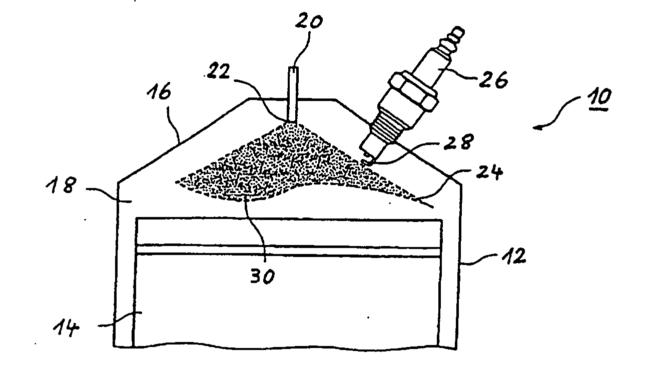
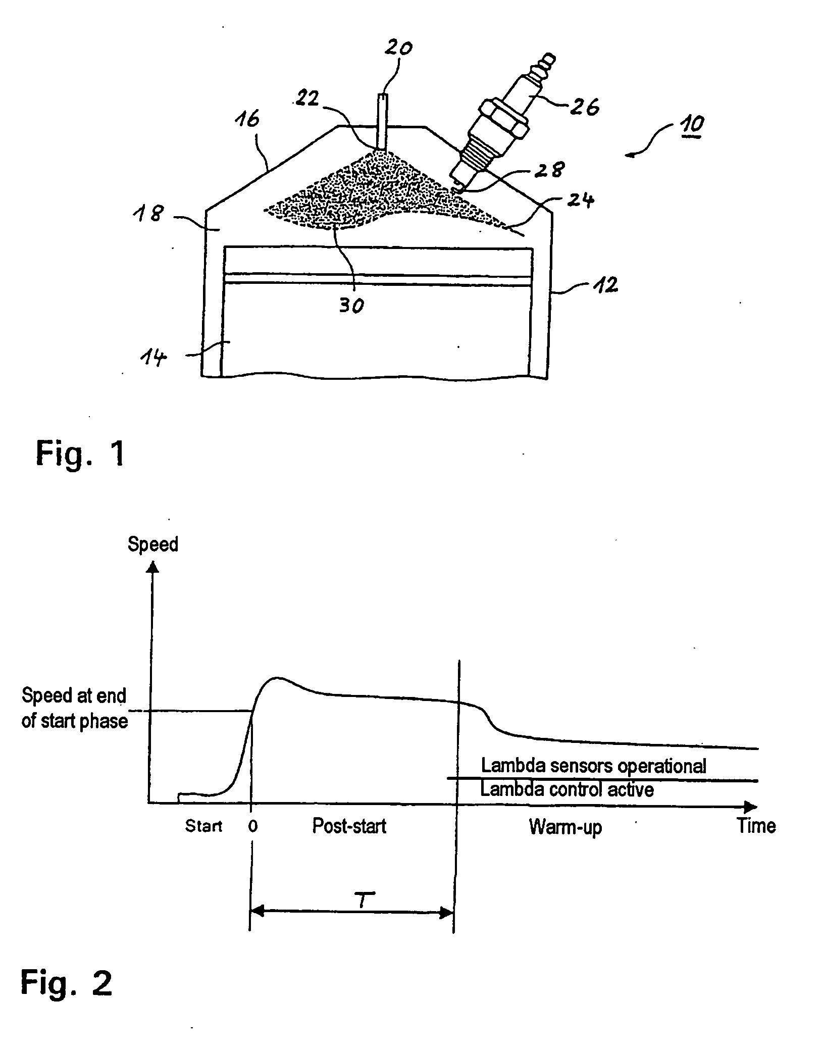
[0027]FIG. 1 shows in a considerably simplified view a cylinder 12 of a spark-ignition internal combustion engine 10 with direct fuel injection. In the cylinder 12, a combustion chamber 18 is delimited by a piston 14 and a cylinder head 16 which closes off the cylinder 12. A fuel injector 20, which can inject fuel into the combustion chamber 18 through a nozzle opening 22, is arranged centrally in the cylinder head 16. A control device (not illustrated) determines, inter alia, the injection times of the fuel, with the associated fuel quantities, and an ignition time at which an air / fuel mixture, which is formed in the combustion chamber, is ignited by means of a spark plug 26 or the like.

[0028] When the nozzle opening 22 of the fuel injector 20 is unblocked, the fuel is injected into the combustion chamber 18 in the form of a conical jet 24 with an opening angle of between 70° and 110°. The spark plug 26 is positioned in the combustion chamber 18 such that the electrodes 28 of the ...


PUM


Abstract

In a method for operating a spark-ignition internal combustion engine with direct fuel injection in the post-start phase at low temperatures, fuel is supplied to the combustion air in a pilot injection (MH) of a first fuel quantity during an intake stroke of the internal combustion engine such that the pilot injection (MH) forms a homogeneous, lean air/fuel mixture (λ>1) in substantially the entire combustion chamber, and a main injection (MS) of a second fuel quantity is subsequently injected into the combustion chamber during a compression stroke directly before the ignition time (ZT), said main injection (MS) forming in the region of the spark plug a stratified, rich air/fuel mixture (λ<1), which is then ignited by the spark plug.

Description

[0001] This is a Continuation-in-Part application of pending international patent application PCT / EP2005 / 003542 filed Apr. 05, 2005 and claiming the priority of German patent application 10 2004 017 990.5 filed Apr. 13, 2004.BACKGROUND OF THE INVENTION [0002] The invention relates to a method for operating a spark-ignition internal combustion engine, in particular a spark-ignition internal combustion engine with direct fuel injection in the post-start phase at low temperatures. [0003] In a conventional injection strategy in direct-injection gasoline engines and gasoline engines with intake pipe injection, the engine is operated in the so-called homogeneous operating mode in the initial seconds after a cold start at low temperatures of −30° C. to 0° C. Here, in the direct-injection gasoline engine, the injection into the combustion chamber takes place during the intake stroke. As a result of the intake air flowing in and the flows generated in the combustion chamber by the downward m...

Claims


Application Information

Patent Timeline
IPC IPC(8): F02B17/00F02B23/10F02D41/06F02D41/30F02D41/40
CPCF02B23/101F02D41/064F02D41/3023Y02T10/44F02D41/403Y02T10/125F02D41/402Y02T10/12Y02T10/40
Inventor KOHLER, BERNDLUX, CHRISTOPHOECHSLE, MICHAELSPIETH, ANDREAS
Owner DAIMLER AG
Why Eureka
Try Eureka