Frame structure for construction machine

a construction machine and frame technology, applied in the direction of tractors, pedestrian/occupant safety arrangements, vehicular safety arrangements, etc., to achieve the effect of increasing the overall strength of the construction machine, good efficiency, and reducing vibrations

Active Publication Date: 2007-03-15
KOMATSU LTD
View PDF10 Cites 32 Cited by
  • Summary
  • Abstract
  • Description
  • Claims
  • Application Information

AI Technical Summary

Benefits of technology

[0025] Thus, when the rear portion of the cab is disposed on the gate frame, shocks from the ground when moving forward will can be received in the mount units with good efficiency, and vibrations can be kept to a m...

Problems solved by technology

However, the conventional frame structure for a const...

Method used


Image

  • Frame structure for construction machine
  • Frame structure for construction machine
  • Frame structure for construction machine

Examples


Embodiment Construction

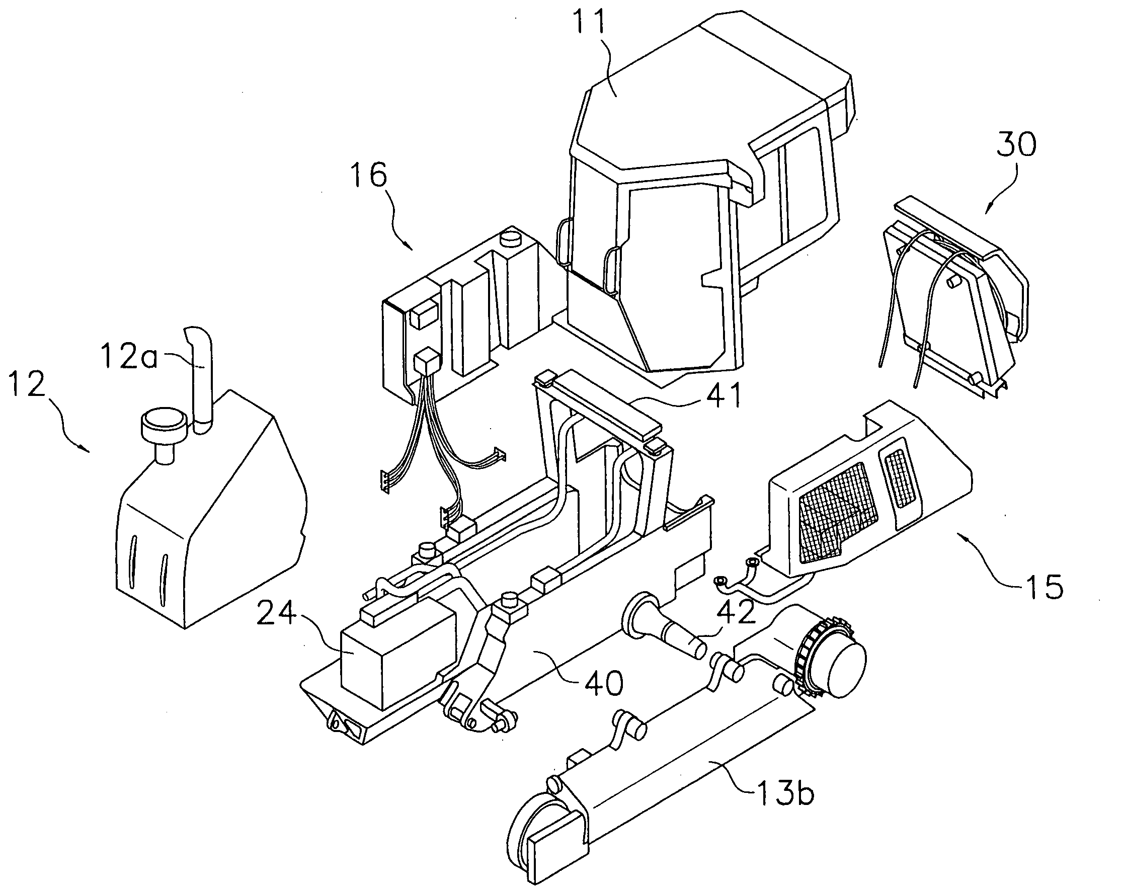
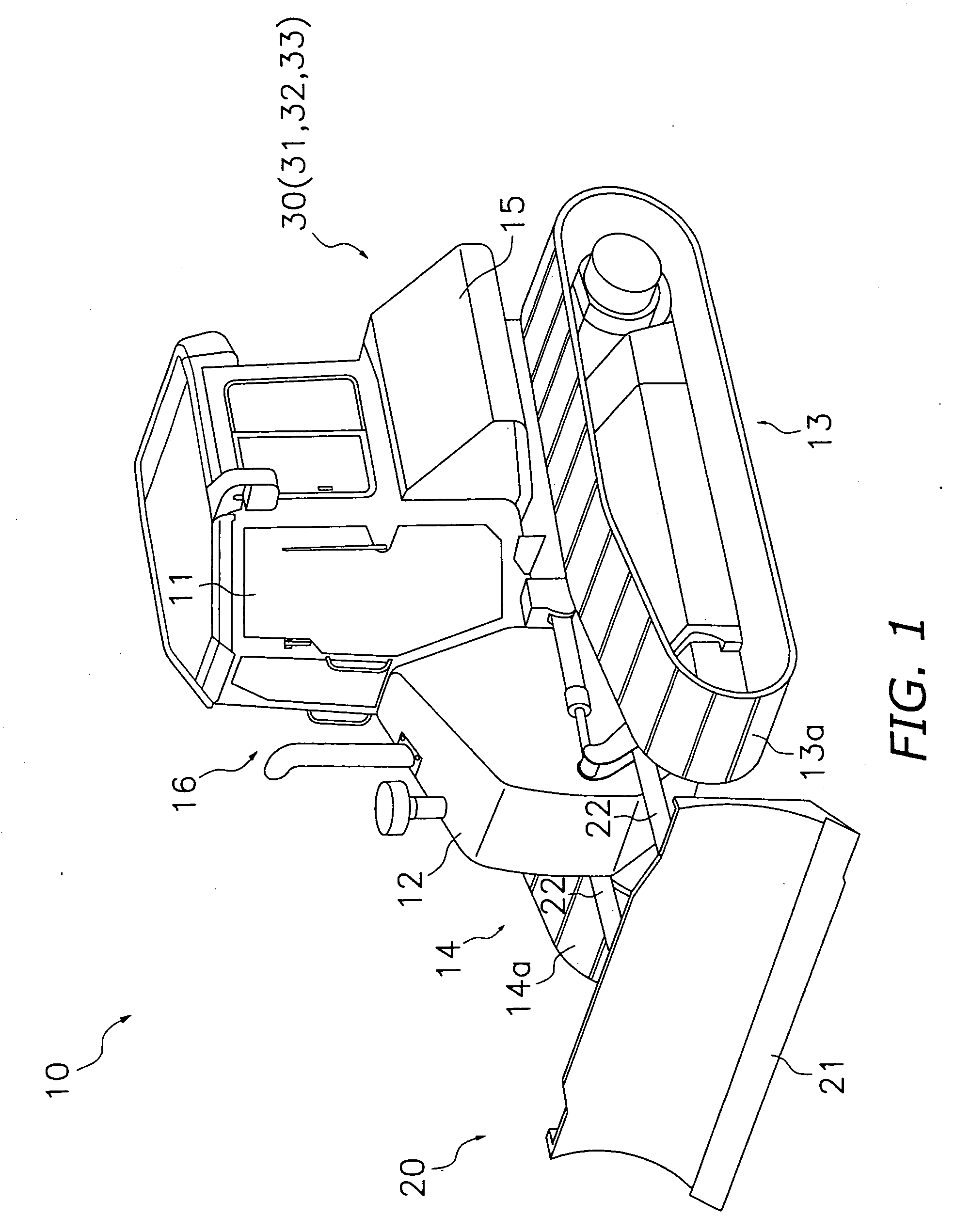
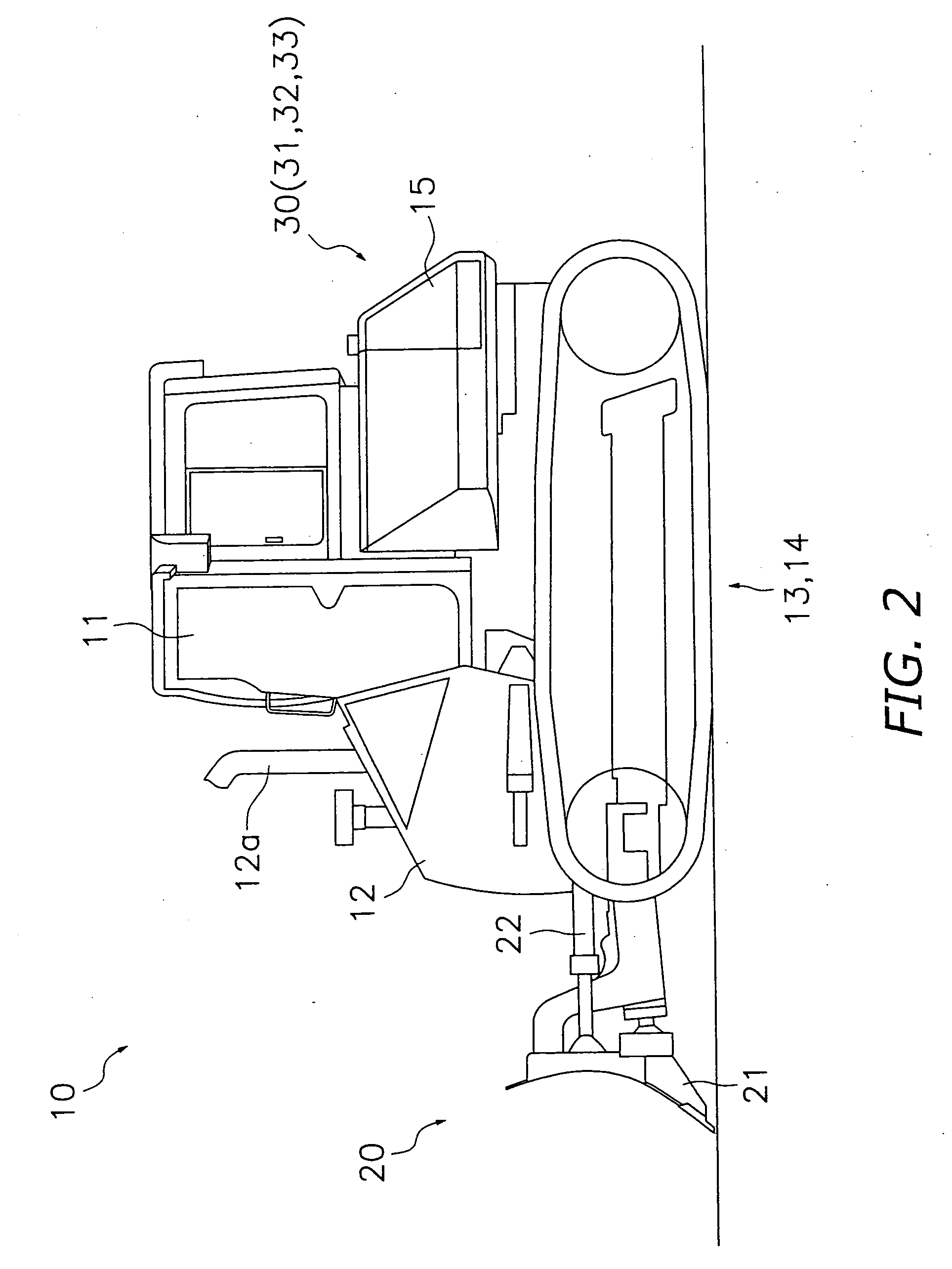
[0035]FIGS. 1-6 will be employed below to describe a frame structure of a bulldozer (construction machine) 10 according to one embodiment of the present invention. Note that with regard to the terms “front” and “rear” employed in the description below, the term “front” describes the front side of the bulldozer 10, and the term “rear” describes the rear side thereof.

Overall Construction of the Bulldozer 10

[0036] As shown in FIGS. 1 to 3, the bulldozer 10 of the present embodiment is comprised of a cab (driver's cab) 11, nose module 12, left and right drive devices 13, 14, fuel tank module (fuel tank) 15, a hydraulic oil module (hydraulic oil tank) 16, a work device 20, a radiator module 30, and a main frame 40 (see FIG. 4).

[0037] Built into the interior of the cab 11 is a seat for the operator of the bulldozer 10 to sit, and levers, pedals, and gauges for various operations. The cab 11 has a rollover protection structure (hereinafter referred to as a ROPS), and is disposed on the ...


PUM


Abstract

A bulldozer is provided with a boat shaped main frame and a substantially U-shaped gate frame as a frame structure that mounts a cap having a rollover protection structure (ROPS) and forms the skeleton of the bulldozer. The gate frame is installed on the upper portion of the main frame, has a pair of left and right columns that are disposed along a substantially vertical direction, and has a beam that connects the upper ends thereof. Mount units for mounting the cab and stopper units for firmly grasping the cab are arranged on the upper surface of the beam.

Description

BACKGROUND OF THE INVENTION [0001] 1. Field of the Invention [0002] The present invention relates to a frame structure of a construction machine such as a bulldozer or the like. [0003] 2. Background Information [0004] In a conventional construction machine such as a bulldozer or the like, a boat-shaped main frame has various components mounted thereon, such as a slant nose, a track frame, a tank frame, a cab, and the like. [0005] For example, Patent Document 1 discloses a main frame structure for a construction machine in which a pair of left and right main frames are constructed with a single thin straight plate disposed along the longitudinal direction of a vehicle, hollow pillar members are fixed to the left and right outer surfaces thereof, and the positions of the column members are in substantially the same plane as the position of a cross member that pivotably supports an equalizer bar. [Patent Document 1] Japanese Utility Model Application Publication 2000-027229 (published...

Claims


Application Information

Patent Timeline
IPC IPC(8): B62D33/06B60R21/13B60K11/04
CPCB60R2021/0081B60R21/131
Inventor FUKAZAWA, KAZUMASAMUKAINO, MASAYUKIANDREWS, DAVID
Owner KOMATSU LTD
Why Eureka
Try Eureka