
Piezoelectric device for generating acoustic signal

a technology of acoustic signal and piezoelectric device, which is applied in the direction of piezoelectric/electrostrictive transducers, generators/motors, transducer types, etc., can solve the problems of limiting the miniaturization while, reducing the mechanical strength of these elements, and reducing the sound leakage of people around a user, so as to reduce the vibration except in the longitudinal direction, reduce the sound leakage, and facilitate the assembly of the structur

Inactive Publication Date: 2007-03-15
TOKIN CORP
View PDF6 Cites 63 Cited by
  • Summary
  • Abstract
  • Description
  • Claims
  • Application Information

AI Technical Summary

Benefits of technology

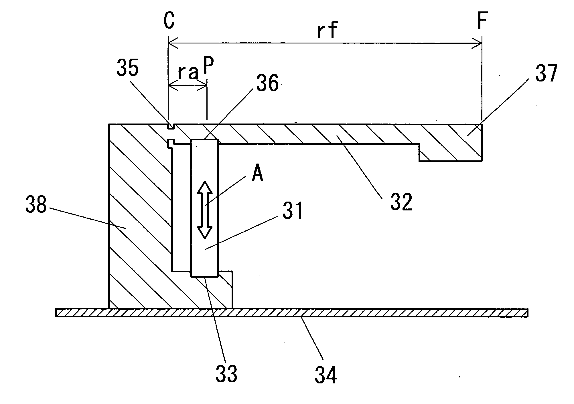
[0013] The present invention enables the use of a small-size and high-power piezoelectric element such as a laminated piezoelectric actuator as a drive source of vibration to thereby achieve miniaturization. This has been not attained in a conventional piezoelectric device for generating an acoustic signal that directly transfers the displacement of mechanical vibration generated by a piezoelectric unimorph element or piezoelectric bimorph element and enlarge the area of vibration to obtain desired acoustic vibration. Specifically, the displacement by expansion and contraction in longitudinal direction in an acoustic frequency range generated by a piezoelectric element such as a laminated piezoelectric actuator is expanded by the expansion mechanism, thereby obtaining a large amplitude. Because the weight of the unit of the base member is set greater than the weight of the unit of the vibration output member, when the displacement of the vibration of the piezoelectric element is expanded, the vibration is not transferred to the base member but concentrated on the vibration output member, thereby expanding the disposition efficiently. Further, sound leakage that is caused by the vibration of the base member is significantly reduced.
[0014] Furthermore, because the present invention does not use flexible transformation such as a piezoelectric unimorph element or a piezoelectric bimorph element, the piezoelectric element such as a laminated piezoelectric actuator can be very small-sized and strong without depending on the shape of the piezoelectric element in use. The use of resonant frequency by design of a vibration system including an expansion mechanism enables obtainment of a larger acoustic output.
[0016] In this invention, the expansion mechanism, which expands the displacement in an acoustic frequency range that the laminated piezoelectric actuator generates, is suitable for the beam structure such as a cantilever structure and a bridge structure or the like. All of the beam structure is formed of a metal, thus enabling the structure to increase the resistance to dropping impact. Furthermore, the most suitable design enables the resonance frequency to set in a low frequency range while the expansion mechanism is small. In general, the more displacement is expanded by the expansion mechanism, the more compressive force decreases. However, the compressive force generated by the laminated piezoelectric actuator acts with the high level, thus the generated force higher than the one generated by piezoelectric element can be introduced, enabling the larger acoustic output to be introduced. Therefore, the vibration output member in the vibration system including the laminated piezoelectric actuator is joined with a panel such as a vibration receiver, a housing, and a part of the human head or so like, enabling the larger acoustic output to be introduced.
[0017] Furthermore, at least a part of the expansion mechanism is formed by pressing a metal plate, thereby enabling the reduction of the manufacturing cost of the expansion mechanism.
[0020] The piezoelectric element is a columnar, and the expansion mechanism includes a thread for applying a compressive force that is adjustable by a fastening force of the thread to the piezoelectric element in a longitudinal direction. Thereby, the application of the compressive force and the generation of it can be easy, easily assembling the structure.
[0021] Furthermore, the piezoelectric element is surrounded by a viscous member or an elastic member in all directions different from a direction of an end of the piezoelectric element. Thereby, especially in the case of the columnar piezoelectric element, the vibration except in the longitudinal direction can be reduced, sound leakage reducing.

Problems solved by technology

Because the displacement of mechanical vibration is determined by the shape of a piezoelectric element, there is a limit to miniaturization while maintaining a desired acoustic output.
The mechanical strength of these elements is low and thus vulnerable to dropping impact.
This causes vibration of a case or housing where an acoustic vibration should not be output, which leads to sound leakage to have people around a user hear the sound.
It is thus unsuitable for application to the piezoelectric device for generating an acoustic signal that requires privacy feature.
When the device is applied to a bone conduction speaker, the vibration occurring in a portion that is different from the portion though which vibration is transferred to a cranial bone and the airway sound are unwanted.

Method used


Image

  • Piezoelectric device for generating acoustic signal
  • Piezoelectric device for generating acoustic signal
  • Piezoelectric device for generating acoustic signal

Examples


Embodiment Construction

[0043] The invention will be now described herein with reference to illustrative embodiments. Those skilled in the art will recognize that many alternative embodiments can be accomplished using the teachings of the present invention and that the invention is not limited to the embodiments illustrated for explanatory purposed.

[0044] An acoustic vibration generating element according to an embodiment of the present invention is applicable to an acoustic vibration generating element or a loudspeaker that is used in a cell phone, a portable terminal and so on, a headphone that functions as acoustic equipment, acoustic equipment that uses bone conduction, and so on.

[0045] An exemplary embodiment of the present invention is described hereinafter in detail with reference to the drawings.

[0046]FIG. 4 is a pattern diagram showing a basic structure of a piezoelectric device for generating an acoustic signal according to an embodiment of the invention. The piezoelectric device for generatin...


PUM


Abstract

There is provided a piezoelectric device for generating an acoustic signal in which an expansion mechanism expands a disposition of a laminated piezoelectric actuator by the principle of leverage. The mass of a base member placed in the expansion mechanism is larger than the mass of a vibration output member. An overall device size is small. The piezoelectric device has a pressurization structure for reducing a tractive force acting on the laminated piezoelectric actuator which is generated by the amplification. This enables provision of a piezoelectric device for generating an acoustic signal that is a small size, highly resistant to dropping impact, and has god acoustic performance with less sound leakage.

Description

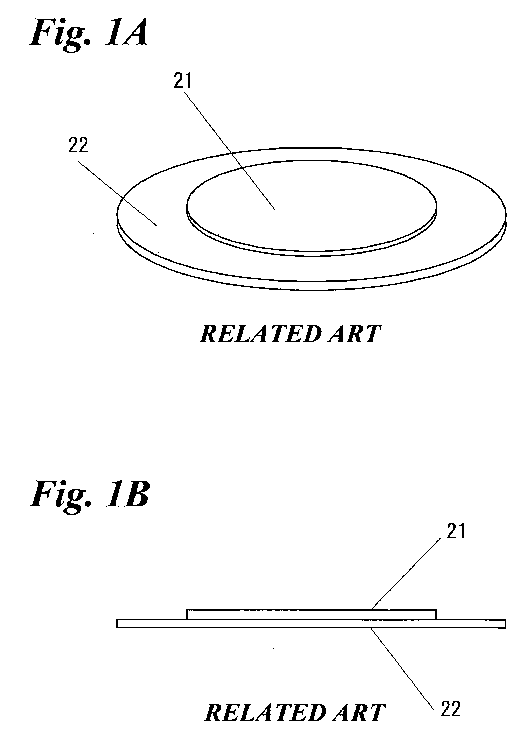
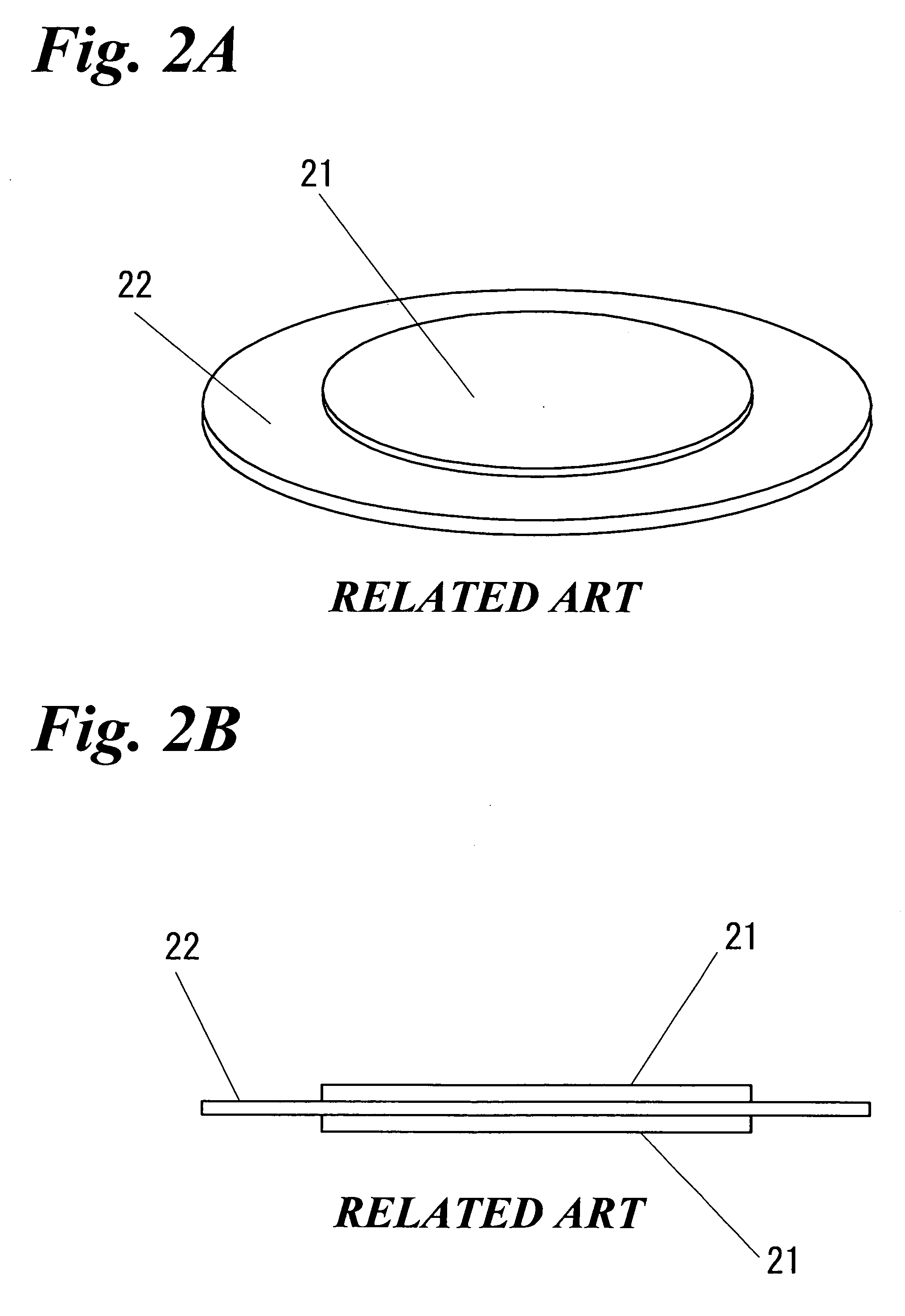
BACKGROUND OF THE INVENTION [0001] 1. Field of the Invention [0002] The present invention generally relates to a device for generating an acoustic signal which is applicable to a loudspeaker that generates acoustic vibration in air, a headphone that is directly held against the ear for listening, a bone conduction speaker that transfers acoustic vibration through a cranial bone to be listened by auditory nerve, and so on. Particularly, the present invention relates to a piezoelectric device for generating an acoustic signal which uses a piezoelectric element. [0003] 2. Description of Related Art [0004] A piezoelectric device for generating an acoustic signal using a piezoelectric element typically employs a piezoelectric unimorph element or a piezoelectric bimorph element. FIGS. 1A and 1B are a perspective view and a side view, respectively, of a piezoelectric unimorph element. The piezoelectric unimorph element has a structure that a thin circular piezoelectric ceramic plate 21 hav...

Claims


Application Information

Patent Timeline
Patent Type & Authority Applications(United States)
IPC IPC(8): H01L41/08H10N30/00
CPCH04R2460/13H04R17/00
Inventor KAWASE, HIDEYUKINITOBE, YUJI
Owner TOKIN CORP
Learn More