Illumination device and display device provided with the same

Active Publication Date: 2007-03-15
DAWNCREST IP LLC
View PDF8 Cites 83 Cited by
  • Summary
  • Abstract
  • Description
  • Claims
  • Application Information

AI Technical Summary

Benefits of technology

[0007] Therefore, an object of the present invention is to realize an illumination device in which high color reproducibility is obtained by additive mixing of three colors and intensity efficiency and reliability are high. That is, an illumination device according to the present invention has a structure in which a first color conversion element for converting blue light into red light is disposed on an optical path between a second color conversion element for converting blue light into green light and a blue light emitting element and separated from the second color conversion element. According to the structure, the blue light emitted from the blue light emitting element and the red light obtained by the first color conversion element are mixed to obtain v

Problems solved by technology

Therefore, an LCD module having high color reproducibility cannot be realized.
In general, when the pseudo white LED is used as a light source, it is very difficult for a current color filter to exceed an NTSC ratio of 100%.
However, the chalcogenide phosphor doped with the rare-earth element causes a chemical

Method used


Image

  • Illumination device and display device provided with the same
  • Illumination device and display device provided with the same
  • Illumination device and display device provided with the same

Examples


embodiment 2

(Embodiment 2)

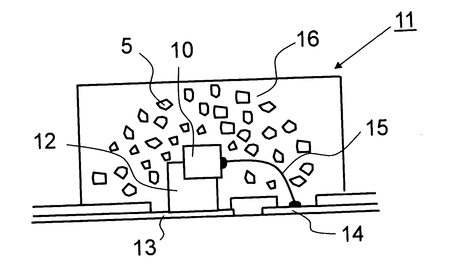
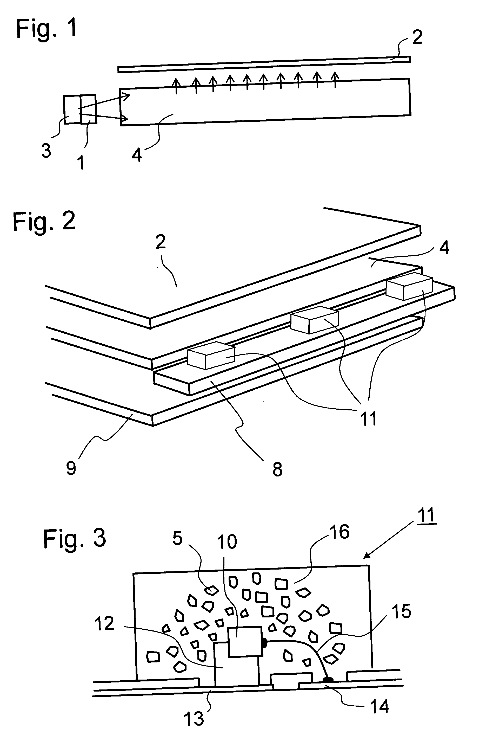
[0059]FIG. 9 is a schematic cross sectional view showing the entire structure of an illumination device according to this embodiment. A point different from the structure of the illumination device according to Embodiment 1 is that a prism instead of the reflecting plate is provided on a rear surface of the light guide member 4. The light emitting diode packages 11 having the structure shown in FIG. 3 are turned on to allow light to enter the light guide member 4. The incident light is uniformly exited from a light exit surface of the light guide member 4 which is an upper portion thereof in the cross sectional view of FIG. 10 by a prism 17 designed with an optimum angle and an optimum height. Then, the light passes through the second color conversion element 2 to convert a part of blue light into green light. Therefore, white light can be obtained from blue light, red light, and green light by additive mixing of three colors. The light guide member 4 and the light emi...

embodiment 3

(Embodiment 3)

[0060] Next, a liquid crystal display device using a liquid crystal display panel as a non-self light emission display element will be described. FIG. 10 is a schematic cross sectional view showing a structure of the liquid crystal display device. A liquid crystal display panel 30 is located on the light emitting surface of the illumination device shown in FIG. 1. The description overlapped with that in FIG. 1 is omitted here. The liquid crystal display panel 30 includes a color filter. In the case of a display device capable of performing color display, it is necessary to perform tuning on colored portions of the color filter based on a spectrum of a light source. In particular, it is important to adjust a green colored portion.

[0061] When a pseudo white LED made of a YAG phosphor is used as a conventional light source, it is necessary to manufacture the color filter provided in the liquid crystal display panel based on the light emission spectrum (FIG. 7) of the pse...


PUM


Abstract

An illumination device for obtaining white light using two kinds of phosphors for converting blue light into green light and red light based on blue excitation is provided to realize high light emission efficiency and a long life. The illumination device has a structure in which a first color conversion element for converting light into red light based on blue excitation is disposed on an optical path between a second color conversion element for converting light into green light based on blue excitation and a blue light emitting element and separated from the second color conversion element. A resin for sealing a blue LED is mixed with a red phosphor to exit violet light (blue light and red light). A resin containing a green phosphor is disposed on an optical path of violet light. The white light is realized at high light emission efficiency by additive mixing of three colors.

Description

BACKGROUND OF THE INVENTION [0001] 1. Field of the Invention [0002] The present invention relates to an illumination device for illuminating a non-self light emission display element and a display device which is provided with the illumination device and used for an electronic device. In particular, the present invention relates to a liquid crystal display device used for a portable information device, a mobile telephone, and the like and an illumination device such as a frontlight unit or a backlight unit to illuminate the display element. [0003] 2. Description of the Related Art [0004] In recent years, most of display devices used for a mobile telephone, a mobile computer, and the like are liquid crystal display devices capable of obtaining a high-definition color image with reduced power consumption. A liquid crystal element used for the liquid crystal display devices is a non-self light emission type, so the liquid crystal element is illuminated by an illuminating device using a...

Claims


Application Information

Patent Timeline
IPC IPC(8): H01J1/62H01L33/32H01L33/50H01L33/56
CPCG02B6/0023H01L33/504G02B6/0068H01L2224/45144H01L2224/48091H01L2224/48464H01L2924/00014H01L2924/00
Inventor KURIHARA, MATOKOKATO, KAZUYA
Owner DAWNCREST IP LLC
Why Eureka
Try Eureka