Magneto-Optic Remote Sensor For Angular Rotation, Linear Displacements, And Evaluation Of Surface Deformations

a magnetic optical and remote sensor technology, applied in the field of displacement sensors, can solve the problems of failure of structural components, failure of other techniques described above, insufficient sensitive to surface deformation, etc., and achieve the effect of enhancing aircraft safety

Inactive Publication Date: 2007-03-15
IOWA STATE UNIV RES FOUND
View PDF1 Cites 10 Cited by
  • Summary
  • Abstract
  • Description
  • Claims
  • Application Information

AI Technical Summary

Benefits of technology

[0010] In one aspect, provided is a magneto-optic sensor technique that provides the capability for the estimation of angular rotation, linear displacement and for the evaluation of surface deformations for all types of materials: magnetic, non-magnetic, conducting, and non-conducting materials. The technique uses a combination of laser beam technology and magnetics to remotely detect surface deformation. The modulated AC output signals as a function of time are very sensitive to the change in intensity of reflected light. The technique can detect internal defects that are not visible by measurement of surface. For example, it can enhance aircraft safety by evaluation of deformations on the surface of the aircraft skin and other objects by remotely detecting surface changes to a level below 0.002 degrees.

Problems solved by technology

Surface deformation caused by sub-surface and internal defects can often be the cause of failure in structural components.
The other techniques described above do not work on both magnetic and non magnetic metallic materials.
Magnetic leakage fields from a surface defect cause rearrangement of domain structure in the magneto-optic film, giving rise to contract in the domain images of the magneto-optic film which are indicative of defects in the surface.
The problem with this technique is that it is insufficiently sensitive for surface deformation caused by sub-surface and internal defects (i.e., micro-scale surface deformation) due to negligible magnetic flux leakage fields.
Furthermore, this technique is not applicable to non-conducting materials (e.g., ceramics, polymer-matrix composites, etc.) due to the absence of magnetic flux leakage fields emanating from the non-conducting materials.

Method used


Image

  • Magneto-Optic Remote Sensor For Angular Rotation, Linear Displacements, And Evaluation Of Surface Deformations
  • Magneto-Optic Remote Sensor For Angular Rotation, Linear Displacements, And Evaluation Of Surface Deformations
  • Magneto-Optic Remote Sensor For Angular Rotation, Linear Displacements, And Evaluation Of Surface Deformations

Examples


Embodiment Construction

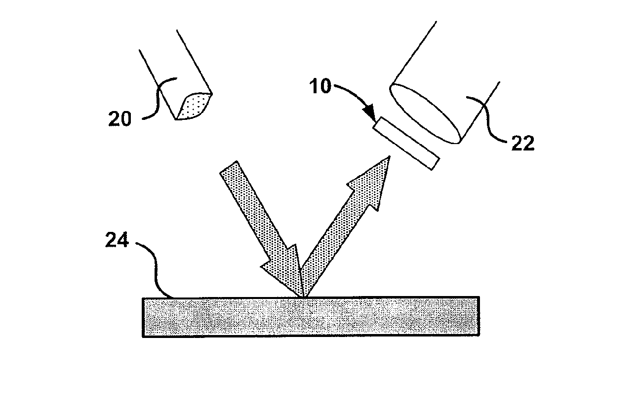
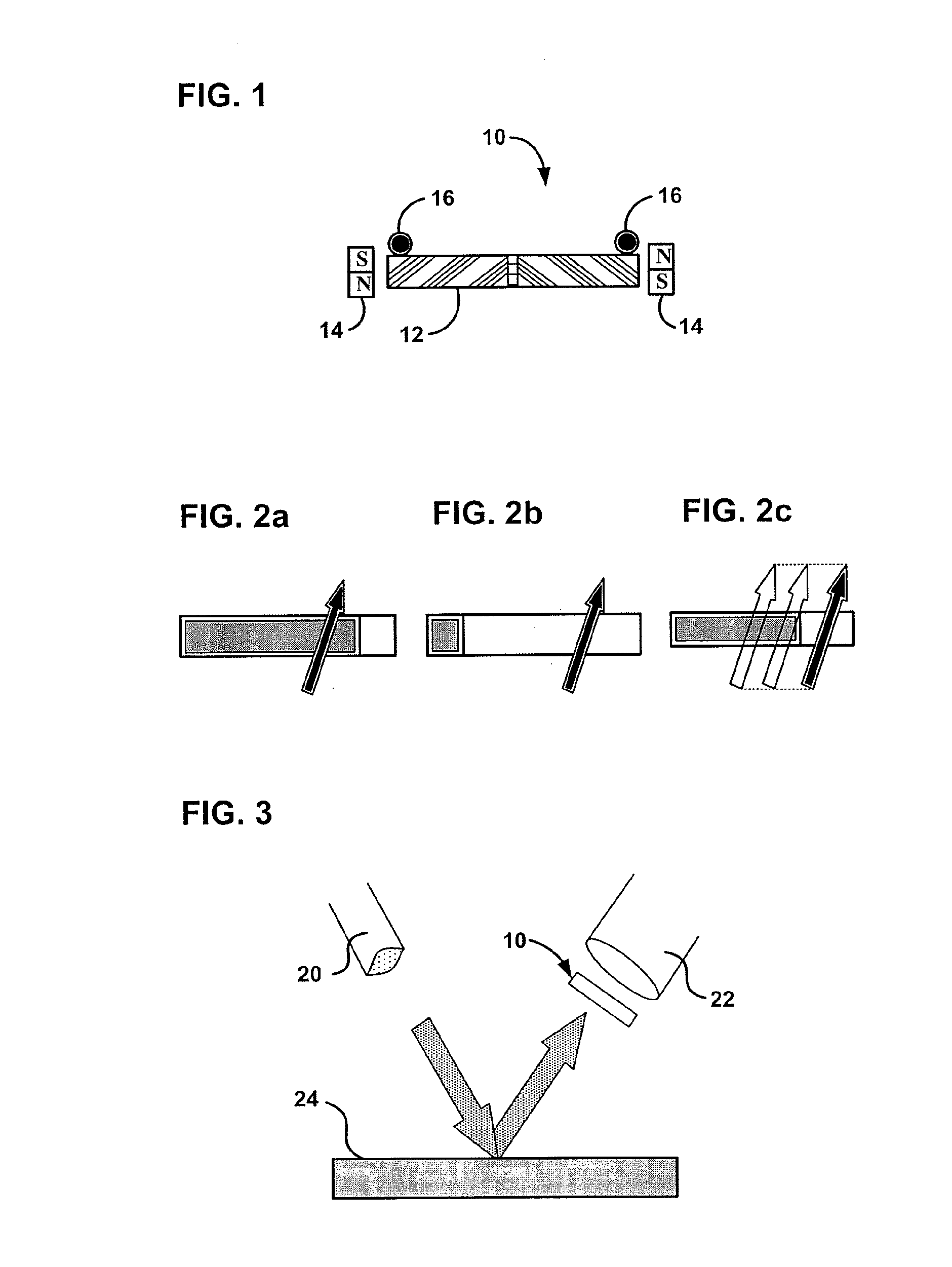
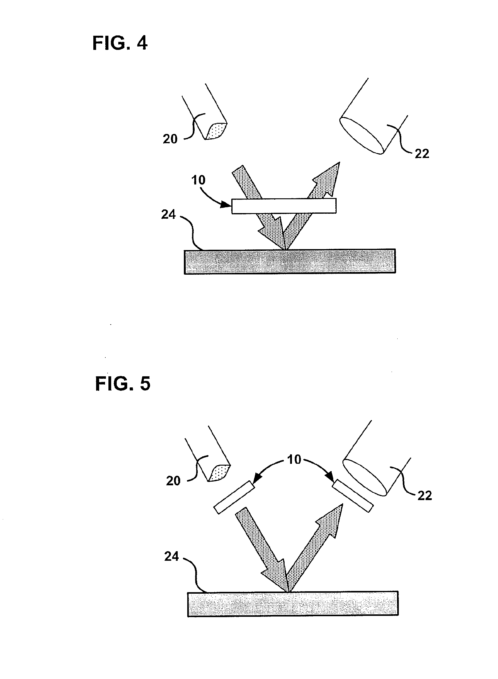
[0026] Described herein is a magneto-optic (MO) nondestructive evaluation (NDE) technique that is based on the periodically modulated Faraday Effect for detecting surface deformation created by sub-surface or internal defects. This magneto-optic technique provides a non-contact method for investigation of materials which enables a remote sensor system to be developed. The technique has been applied to detection of surface defects, weak magnetic fields, electric currents, and rotational speed. Remote evaluation of microscopic surface deformation is possible with the invention because the technique does not require close contact between the sample surface and the magneto-optic sensor film in order to perform the evaluation of surface deformation. The technique was found to provide sufficient sensitivity for a small deformation by using simulated surface deformation by rotation of 0.002 degrees of a test sample surface. The angle of 0.002 degrees is the difference between the light ref...


PUM

PropertyMeasurementUnit
frequencyaaaaaaaaaa
angleaaaaaaaaaa
thicknessaaaaaaaaaa

Abstract

A system and method to detect angular rotation, linear displacement and/or surface deformations is presented. The method is based on the ability of a linear polarized light to interact with magnetic materials and to change its polarization angle due to Faraday effect. A basic structure of the system consists of a magneto-optic (MO) film with a two-domain structure and a single domain wall which are generated by gradient magnetic field produced by opposite polarity permanent magnets placed near the film. An AC magnetic field applied perpendicular to the MO film surface causes the magnetic domain wall in the MO film to oscillate at the same frequency. This leads to a detected output AC modulated signal. By measuring the temporal changes in this signal, information on angular rotation, linear displacement and/or surface deformation can be obtained.

Description

CROSS-REFERENCE TO RELATED PATENT APPLICATIONS [0001] This patent application claims the benefit of U.S. Provisional Patent Application No. 60 / 701,794, filed Jul. 22, 2005, the entire disclosure which is incorporated by reference in its entirety herein.STATEMENT REGARDING FEDERALLY SPONSORED RESEARCH AND DEVELOPMENT [0002] This invention was made in part with Government support under Grant Numbers NAG-1-02098 awarded by the National Aeronautical and Space Administration. The Government may have certain rights in this invention.FIELD OF THE INVENTION [0003] The subject matter generally relates to displacement sensors, and more particularly, to displacement sensors that detect angular rotation, linear displacement and microscopic surface and subsurface deformation in materials. BACKGROUND [0004] Surface deformation caused by sub-surface and internal defects can often be the cause of failure in structural components. Small and reliable sensors for remote detection of angular and / or spa...

Claims


Application Information

Patent Timeline
Patent Type & Authority Applications(United States)
IPC IPC(8): G01N27/82
CPCG01D5/145G01N21/21G01N21/1717
Inventor LEE, SEONG-JAESONG, SANG-HOONMELIKHOV, YEVGENPARK, CHOON-MAHNHAUSER, HANSJILES, DAVID
Owner IOWA STATE UNIV RES FOUND
Why Eureka
Try Eureka