Remote meter reader using a network sensor system and protocol

a network sensor and remote meter technology, applied in the field of automatic meter reading, can solve the problems of limited use of remote imagers, limited applications for remote imaging, and meter-readers may be subject to dog bites, human attacks, or other dangers, and achieve efficient and accurate remote meter reading, cost, accuracy, and safety. the effect of prolonging the operation li

Active Publication Date: 2007-03-15
AVAAK
View PDF8 Cites 92 Cited by
  • Summary
  • Abstract
  • Description
  • Claims
  • Application Information

AI Technical Summary

Benefits of technology

[0006] Briefly, the present invention provides a system and method for automatically reading meters, such as utility meters by using a low power wireless camera, sensor, or imager. The camera unit is attached or otherwise associated with a meter. From time to time, the camera unit takes an image of the meter's reading area, and communicates the image or image data to a local area receiver. The camera unit is battery powered, and operates communication protocols that enable extended operational life. These protocols allow for the camera's radio and processor to be turned on only when necessary, and then for only brief periods of time. At most times, the camera is in a power-conserving sleep mode. Multiple camera units may be arranged to communicate meter image data to the local area receiver, either using asynchronous or synchronous processes. In this way, star, point-to-point, and ring topologies are enabled. The meter image data is communicated from the receiver to a central office using a wide area connection, where the image data is used for determining the meter reading. In one example, the image may be included with a utility bill as confirmed evidence of the current meter reading.
[0007] Advantageously, the camera units of the present invention may be attached to legacy meters, enabling very efficient and accurate remote meter reading. Because of the low-power protocols and structures in the camera units, in normal use the camera units will operate autonomously for up to several years. Accordingly, meter reading can be made more efficient and safe, and fully automated remote meter reading is possible, even with older legacy meters. This allows the cost, accuracy, and safety benefits of remote meter readings to be used on existing meters. In addition, frequent readings, even several times a day, are conveniently possible. This enables utility companies to track hourly usage or even charge per time of use (especially for electricity). In addition, simple imaging DSP (digital signal processing) can be applied to the meter image, and used to read the meter by the utility. This information may then be used to compare to previous readings by a computer, and create a bill without human intervention thus improving reliability and productivity. In one example, the bill may even include an image of the final meter reading.

Problems solved by technology

However, the use of remote imagers has been limited to applications where the remote camera has a stable power source, such as connection to a utility grid, or where the camera system can be conveniently accessed to change or charge its battery.
Accordingly, the applications for remote imaging have been limited.
This is an expensive and time consuming process, and since the meters are often located in private property areas, the meter-readers may be subject to dog bites, human attack, or other dangers.
Due to the high cost of using human readers, some utilities use estimated bills.
Either way, the estimated bills are a stop-gap so the utility can save money, and often leads to great consumer dissatisfaction.
However, these meters are quite expensive, and there are millions of legacy meters installed.
It will take many years, if not decades, to replace and update all these meters.
To date, there is no practical way to automatically read these meters.

Method used


Image

  • Remote meter reader using a network sensor system and protocol
  • Remote meter reader using a network sensor system and protocol
  • Remote meter reader using a network sensor system and protocol

Examples


Embodiment Construction

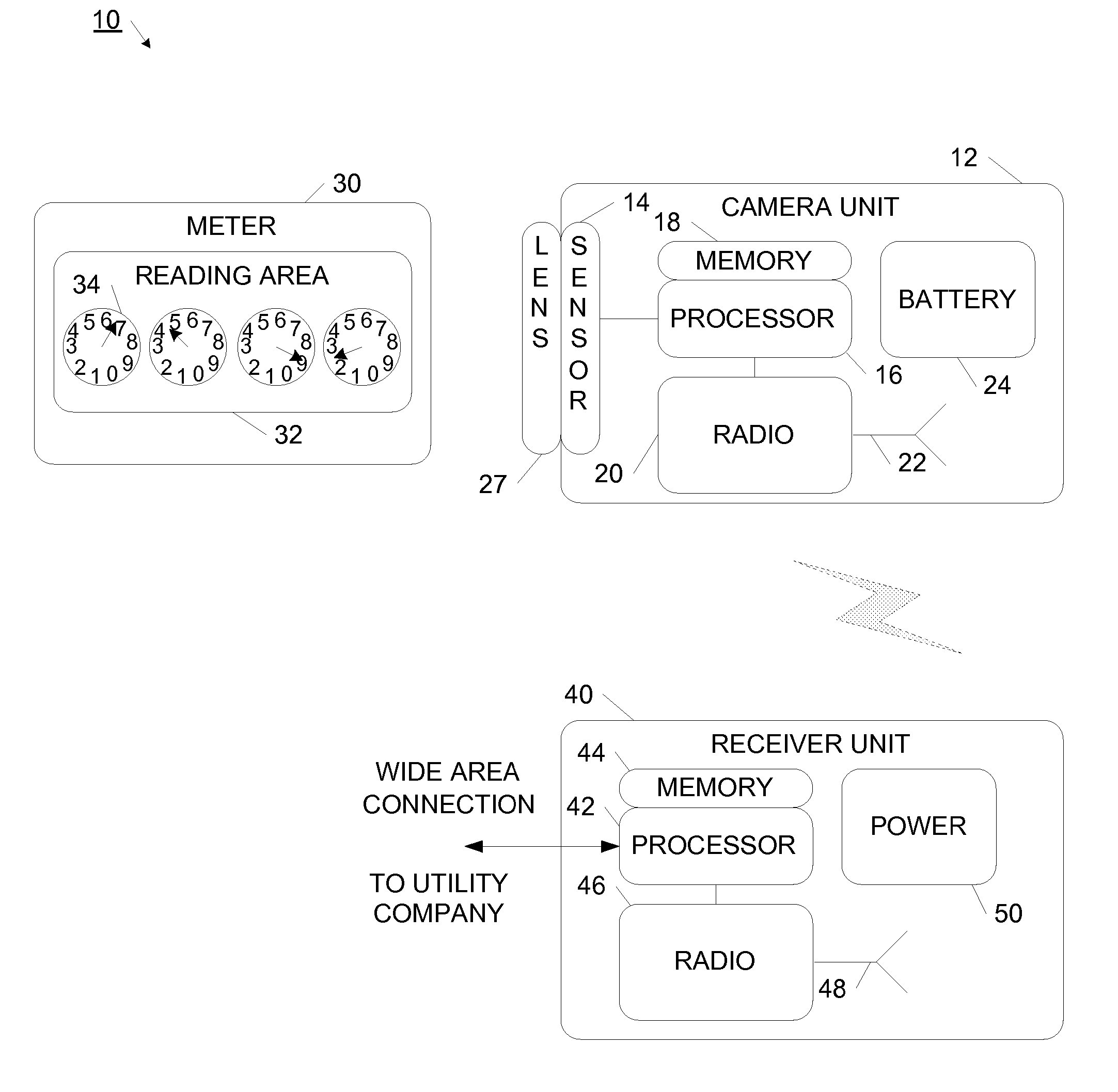
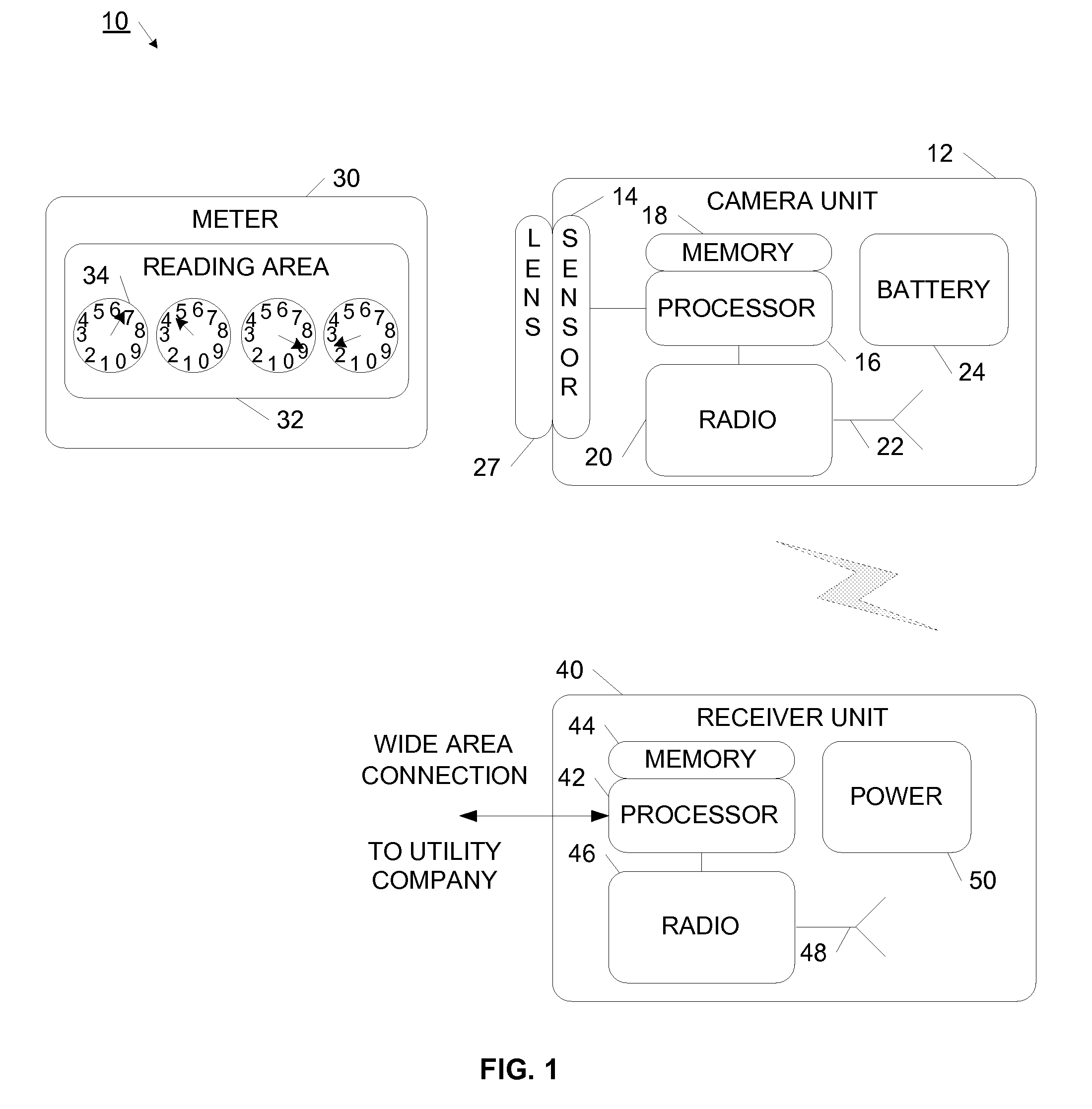
[0017] Referring now to FIG. 1, an automated meter reading system is illustrated. System 10 generally comprises an imaging camera unit 12 attached to or otherwise coupled to a meter 30. In one arrangement, the camera includes a lens or lens system and a CCD or CMOS imager. From time to time, camera unit 12 takes an image of the reading area 32 of meter 30. Reading area 32 has dials, such as dial 34, or a digital display for presenting utility usage information. The image is captured by camera unit 12, and communicated back to a receiver unit 40. In one example, receiver unit 40 is a handheld device used by a human meter reader. In this way, a person driving in a vehicle or walking a distance away from the meter can remotely and wirelessly read the meter. In another example, the receiver unit is in the residential or commercial unit for meter 30, and wirelessly receives image data. The image data may then be communicated through a wide area connection back to the utility company. In ...


PUM


Abstract

A system and method is provided for automatically reading meters, such as utility meters. A camera unit is attached to or otherwise associated with an existing meter. From time to time, either automatically, or upon wireless command, the camera unit takes an image of the meter's readings, and communicates wirelessly the image or image data, to a local area receiver. The images can be transmitted immediately, or stored for later transmission, depending on the network protocol. The camera unit is battery powered, and operates communication protocols that enable extended operational life. These protocols allow for the camera's radio and processor to be turned on only when necessary, and then for only brief periods of time. At most times, the camera is in a power-conserving sleep mode. Multiple camera units may be arranged to communicate meter image data to the local area receiver, either using asynchronous or synchronous processes. In this way, star, point-to-point, MESH and ring networking topologies are enabled. The meter image data is communicated from the receiver to a central office using a wide area connection, where the image data is used for determining the meter reading. In one example, the image may be included with a utility bill as confirmed evidence of the current meter reading.

Description

RELATED APPLICATIONS [0001] This application claims priority to U.S. provisional patent application No. 60 / 698,134, filed Jul. 12, 2005, and entitled “Wireless Automatic Meter Reader (WAMR) Using Miniature Camera”, which is incorporated herein in its entirety.FIELD OF THE INVENTION [0002] The present invention relates to automatic meter reading and specifically to an imager or miniature camera attached to a meter, and to the wireless communication of meter data to a central location. More particularly, the present invention relates to a low power meter imager that wirelessly communicates meter image data. BACKGROUND [0003] The field of remote sensing is growing rapidly. Remote sensing has been found to be useful in security applications, as well as for monitoring environmental, commercial and industrial processes. Remote sensing may include capturing visible light images, temperature, vibrations, seismic, infrared images, chemical or acoustic data. The remote data is either stored l...

Claims


Application Information

Patent Timeline
Patent Type & Authority Applications(United States)
IPC IPC(8): G08C15/06G08B23/00
CPCG01D4/002G01D4/008G01D5/39H04Q9/00Y02B90/246H04Q2209/60Y02B90/241Y04S20/32H04Q2209/40H04Q2209/25H04Q2209/883Y04S20/42G01D2204/45H04Q2209/50Y02B90/20Y04S20/30
Inventor GOLDBERG, BAR-GIORAMESSINGER, GIOIA
Owner AVAAK
Why Eureka
Try Eureka