Light source device, display device, terminal device, light source unit, and method for driving light source device

a technology for light source devices and terminal devices, applied in static indicating devices, lighting and heating apparatuses, instruments, etc., can solve the problems of relatively insignificant grayscale inversion, low contrast and other aspects of display performance, and reduced energy consumption, so as to reduce the effect of color change during radiation angle switching

Active Publication Date: 2007-03-15
NEC LCD TECH CORP
View PDF2 Cites 33 Cited by
  • Summary
  • Abstract
  • Description
  • Claims
  • Application Information

AI Technical Summary

Benefits of technology

[0042] According to the present invention, in a light source device that permits switching of...

Problems solved by technology

Energy consumption can be reduced in the reflective type, since external light can be utilized for display, but since contrast and other aspects of display performance are inferior compared to the transmissive type, transmissive and transflective liquid crystal display devices currently represent the mainstream.
However, liquid crystal panels that use these modes have a narrow angle range in which gradation can be correctly distinguished, and grayscale inversion occurs outside the optimum viewing position.
This problem of grayscale inversion was relatively insignificant in mobile phones and other terminal devices whose display content consists mainly of phone numbers and other text.
However, with recent technological developments, terminal devices have come to display ...

Method used


Image

  • Light source device, display device, terminal device, light source unit, and method for driving light source device
  • Light source device, display device, terminal device, light source unit, and method for driving light source device
  • Light source device, display device, terminal device, light source unit, and method for driving light source device

Examples


first embodiment

[0077] The following detailed description of the light source device, display device, terminal device, light source unit, and method of driving the light source device according to the invention makes reference to the accompanying drawings. First, the light source device, display device, terminal device, light source unit, and method of driving the light source device according to the invention shall be described. FIG. 4 is a perspective view showing the display device according to the present embodiment; FIG. 5 is a perspective view showing a light source unit as a constituent element thereof; FIG. 6 is an xy chromaticity diagram depicting the chromaticity coordinates (x, y) of two types of light sources which are constituent elements of this light source unit; FIG. 7 is a sectional view showing a light source, light-guide plate, and optical film as constituent elements of the light source unit; FIG. 8 is a sectional view showing the transparent / scattering state switching element t...

second embodiment

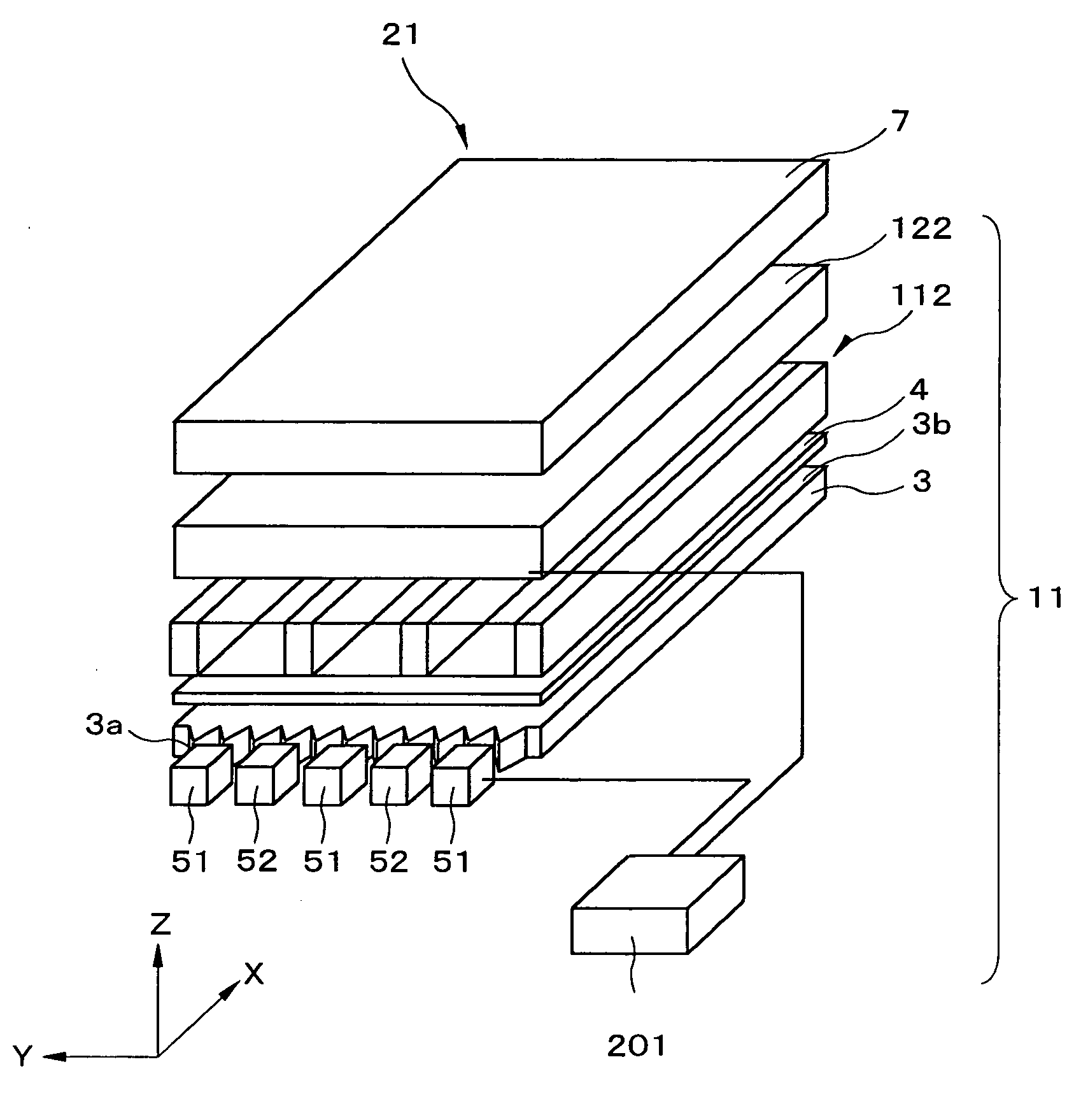
[0129] Next, the invention shall be described. FIG. 12 is a perspective view showing the display device according to the present embodiment of the invention; FIG. 13 is a perspective view showing a light source unit as a constituent element thereof; and FIG. 14 is a perspective view showing a louver as a constituent element thereof and which constitutes a light direction regulating element.

[0130] As shown in FIGS. 12 and 13, as compared to the display device 2, light source device 1, and light source unit 6 according to the first embodiment described previously, a characteristic feature of the display device 21, light source device 11, and light source unit 61 according to the second embodiment feature is that these devices have as a constituent element a louver 112 that constitutes a light direction regulating element. The louver 112 is positioned between the optical film 4 and the transparent / scattering switching element 122.

[0131] As shown in FIG. 14, the louver 112 has transpar...

fourth embodiment

[0136] Next, the invention shall be described. FIGS. 16A through 16G are timing charts depicting operation when the display device according to the present embodiment is switched from a narrow-angle display to a wide-angle display, wherein time is plotted on the horizontal axis of each chart. FIG. 16A has the haze (HAZE: haze value) of the transparent / scattering state switching element plotted on the vertical axis, FIG. 16B has the emission luminosity of the white LED plotted on the vertical axis, FIG. 16C has the emission luminosity of the bluish white LED plotted on the vertical axis, FIG. 16D has the frontal luminance of light prior to entering the transparent / scattering switching element plotted on the vertical axis, FIG. 16E has the chromaticity coordinate (x, y) values of light prior to entering the transparent / scattering switching element plotted on the vertical axis, FIG. 11F has the frontal luminance of light after entering the transparent / scattering switching element plott...


PUM


Abstract

In a display device, white LEDs and bluish white LEDs are arranged in alternating fashion on the light-incident surface side of a light-guide plate. On the light-exit side of the light-guide plate is disposed a transparent/scattering switching element switchable between a state of scattering incident light, and a state of transmitting light unchanged without scattering. During a narrow-angle display, only the white LEDs are lit, and the transparent/scattering switching element is placed in the transparent state, while during a wide-angle display, both the white LEDs and the bluish white LEDs are lit, and the transparent/scattering switching element is placed in the scattering state.

Description

BACKGROUND OF THE INVENTION [0001] 1. Field of the Invention [0002] The present invention relates to a light source device capable of switching the radiation angle of illuminating light; to a display device provided with this light source device and capable of switching the viewing angle; to a terminal device equipped with this display device; to a light source unit incorporating the light source device; and to a method for driving the light source device. [0003] 2. Description of the Related Art [0004] Because of their thin profile, light weight, small size, low energy consumption, and other advantages, display devices that use liquid crystals are currently deployed and used on a wide scale in a range of devices that includes monitors, televisions (TV), and other large terminal devices; notebook-type personal computers, cash dispensers, vending machines, and other mid-sized terminal devices; and personal TVs, PDAs (Personal Digital Assistance: personal information terminal), mobile...

Claims


Application Information

Patent Timeline
IPC IPC(8): G02F1/1333
CPCG02B6/0016G02B6/002G02B6/0038G02B6/005G02B6/0053G02B6/0068G02B6/0076G02F1/133555G02F1/133626
Inventor UEHARA, SHIN-ICHISAITOH, GOROH
Owner NEC LCD TECH CORP
Why Eureka
Try Eureka