Exposure apparatus, exposure method, position control method, and method for producing device

a technology of exposure apparatus and position control method, which is applied in the direction of photomechanical apparatus, printing, instruments, etc., can solve the problems of measurement accuracy and/or exposure accuracy deterioration, exposure accuracy and/or measurement accuracy may be deteriorated, etc., to avoid the deterioration of exposure accuracy and measurement accuracy, correct relative position adjustment, and high exposure accuracy

Inactive Publication Date: 2007-03-15
NIKON CORP
View PDF20 Cites 36 Cited by
  • Summary
  • Abstract
  • Description
  • Claims
  • Application Information

AI Technical Summary

Benefits of technology

[0006] The present invention has been made taking the foregoing circumstances into consideration, an object of which is to provide an exposure apparatus, an exposure method, a position control method, and a method for producing a device, wherein it is possible to highly accurately control the position of a mover capable of holding an exposure objective substrate.
[0019] According to the present invention, there is provided a method for producing a device, comprising using the exposure apparatus as defined in any one of the foregoing aspects. According to the present invention, the control can be satisfactorily performed for the position of the mover capable of holding the substrate when the exposure is performed on the basis of the liquid immersion method, and it is possible to avoid the deterioration of the exposure accuracy and the measurement accuracy. Therefore, it is possible to produce the device having the desired performance.

Problems solved by technology

There is such a possibility that the exposure accuracy and / or the measurement accuracy may be deteriorated due to the deformation.
For example, when an interferometer system, which measures the position by radiating a measuring light beam onto a reflecting surface of a movement mirror provided on the substrate stage, is used when the position of the substrate stage is measured, the measurement accuracy and / or the exposure accuracy is deteriorated if the reflecting surface of the movement mirror is deformed due to the deformation of the substrate stage.

Method used


Image

  • Exposure apparatus, exposure method, position control method, and method for producing device
  • Exposure apparatus, exposure method, position control method, and method for producing device
  • Exposure apparatus, exposure method, position control method, and method for producing device

Examples


Embodiment Construction

[0034] An explanation will be made below about the exposure apparatus according to the present invention with reference to the drawings. However, the present invention is not limited thereto.

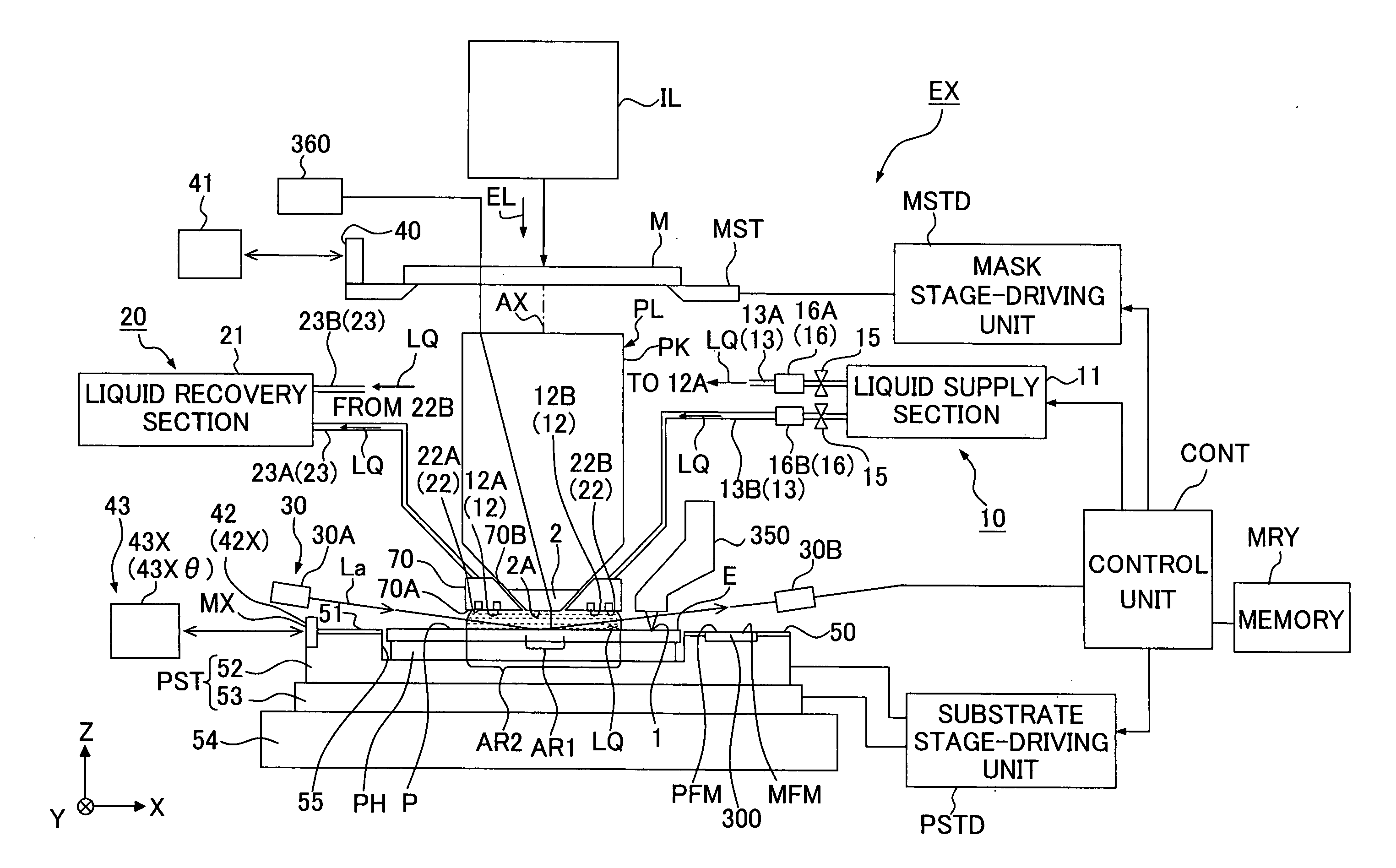
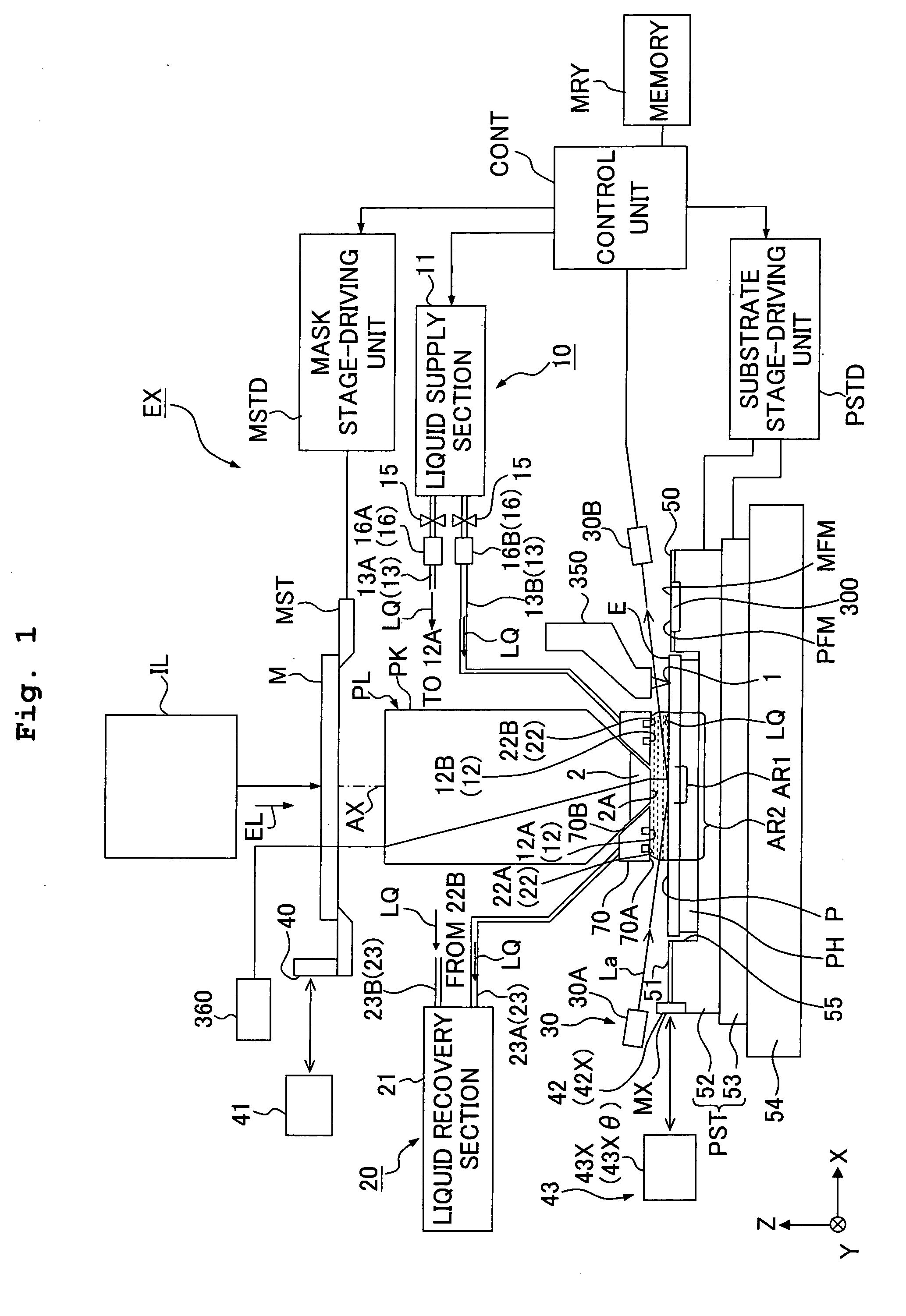
[0035]FIG. 1 shows a schematic arrangement illustrating an embodiment of the exposure apparatus of the present invention. With reference to FIG. 1, an exposure apparatus EX comprises a mask stage MST which is movable while supporting a mask M, a substrate stage PST which has a substrate holder PH for holding a substrate P and which is movable while holding the substrate P with the substrate holder PH, an illumination optical system IL which illuminates, with an exposure light beam EL, the mask M supported by the mask stage MST, a projection optical system PL which performs projection exposure for the substrate P supported by the substrate stage PST with an image of a pattern of the mask M illuminated with the exposure light beam EL, a control unit CONT which integrally controls the overall oper...


PUM

PropertyMeasurementUnit
refractive indexaaaaaaaaaa
angleaaaaaaaaaa
wavelengthaaaaaaaaaa

Abstract

Exposure apparatus EX exposes a substrate P through a liquid LQ. The exposure apparatus is provided with a substrate stage PST which can hold the substrate P, an interferometer system (43), which projects a measuring light on a reflecting plane formed on a moving mirror on the substrate stage PST, receives the reflected light and measures position information of the substrate stage PST, and a memory MRY, which stores error.

Description

TECHNICAL FIELD [0001] The present invention relates to an exposure apparatus, an exposure method, a position control method, and a method for producing a device, in which a substrate is exposed by radiating an exposure light beam onto the substrate through a liquid. BACKGROUND ART [0002] Semiconductor devices and liquid crystal display devices are produced by means of the so-called photolithography technique in which a pattern formed on a mask is transferred onto a photosensitive substrate. The exposure apparatus, which is used in the photolithography step, includes a mask stage for supporting the mask and a substrate stage for supporting the substrate. The pattern on the mask is transferred onto the substrate via a projection optical system while successively moving the mask stage and the substrate stage. In recent years, it is demanded to realize the higher resolution of the projection optical system in order to respond to the further advance of the higher integration of the devi...

Claims


Application Information

Patent Timeline
Patent Type & Authority Applications(United States)
IPC IPC(8): G03B27/42G03F7/20H01L21/027
CPCG03F7/70775G03F7/70341
Inventor YAMAGUCHI, ATSUSHI
Owner NIKON CORP
Why Eureka
Try Eureka