Extraction of foundation in offshore platforms

a technology of offshore platforms and foundations, applied in the field of offshore technology, can solve the problems of limited capacity of jacking-up systems, inability to provide effective foundation extraction, and soil resistance of conventional water jetting systems, so as to reduce the suction on the base, increase the pore pressure, and reduce the effect of suction

Inactive Publication Date: 2007-03-15
OFFSHORE TECH DEVMENT PTE +1
View PDF4 Cites 27 Cited by
  • Summary
  • Abstract
  • Description
  • Claims
  • Application Information

AI Technical Summary

Benefits of technology

[0008] Accordingly, in one aspect, the present invention provides a foundation comprising a body having a base, wherein the body is adapted to receive pressurized fluid; and a plurality of outlets disposed on the base, wherein the plurality of outlets are terminated with an interface layer for allowing pressurized fluid to be released to the base external and preventing the ingress of seabed sediments into the body, whereby the body is configured to provide a uniform distribution of the pressurized fluid to the base external through the plurality of porous outlets, wherein the pressurized fluid released through the plurality of porous outlets increases the pore pressure at the base external, and thereby minimizing the suction on the base.
[0009] In another aspect, the present invention provides a system for extracting an offshore platform foun

Problems solved by technology

Throughout the entire drilling operation, the foundations may penetrate deeply into the seabed, thus experiencing soil resistance therefrom.
Field observations have shown that conventional water jetting system is unable to provide an effective extraction of the foundation.
As such, the extraction rate depends largely on the capacity of the jacking-up system, which is usually limited.
This delay is a huge factor for the increasing cost in the industry.
Furthermore, continuous extraction attempts to overcome large soil resistance may harm the structural integrity of the drilling rig.
For example, the method of distributing pressurized water to fluidize the surrounding soil during extraction could cause channeling effects.
Some of these nozzle openings could create channeling in the soil once the water pressure is released into the surround

Method used


Image

  • Extraction of foundation in offshore platforms
  • Extraction of foundation in offshore platforms
  • Extraction of foundation in offshore platforms

Examples


Embodiment Construction

[0018] The present invention may be understood more readily by reference to the following detailed description of certain embodiments of the invention.

[0019] Throughout this application, where publications are referenced, the disclosures of these publications are hereby incorporated by reference, in their entireties, into this application in order to more fully describe the state of art to which this invention pertains.

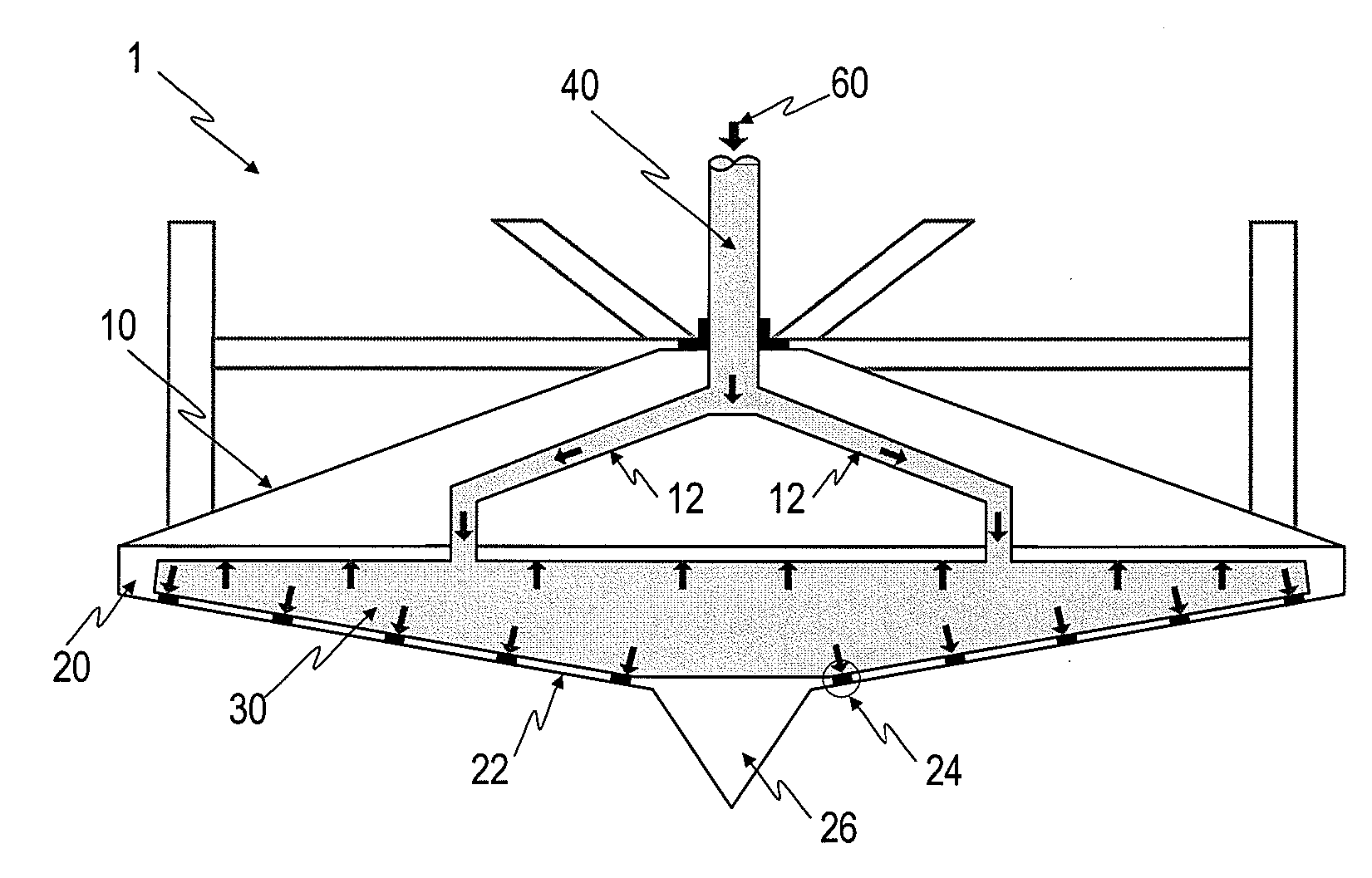
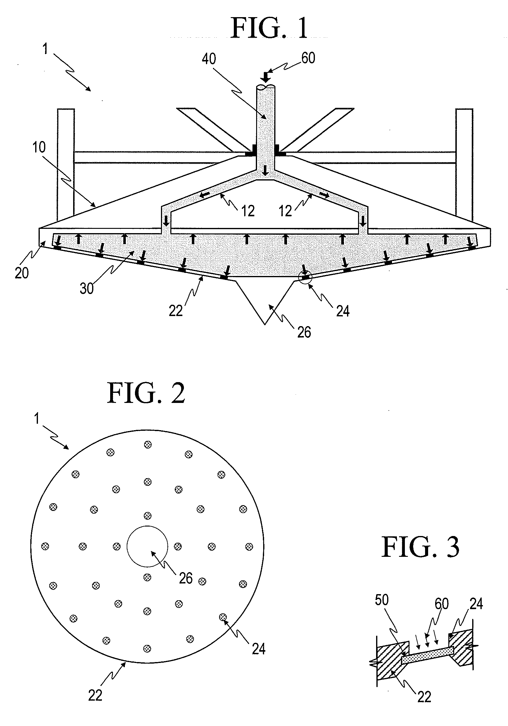
[0020] The present invention provides a foundation for an offshore platform that enables the extraction process to be performed effectively and efficiently. In one embodiment, the foundation 1 comprises an upper body 10 and a lower body 20, wherein the upper body 10 and lower body 20 have a frustum shape (see FIG. 1). It should be understood by one skilled in the art that the foundation 1 can take on other shapes. For instance, a caisson is contemplated. The base 22 of the lower body 20, which also refers to as the base 22 of the foundation 1, comprises a plurality ...


PUM


Abstract

The present invention provides a foundation that facilitates the extraction process by minimizing the soil resistance. When the foundation is lowered onto a seabed, it penetrates the seabed and experiences soil resistance therefrom. In particular, the suction generated at the base of the foundation contributes significantly to the soil resistance. The foundation is configured to uniformly distribute pressurized fluid to the base external via a plurality of outlets. The outlets are terminated with an interface layer to allow the transfer of pressurized fluid to the base external and prevent the ingress or seabed sediments into the body. The pressurized fluid released to the base external increases the pore pressure at the base external, thus minimizing the suction at the base.

Description

FIELD OF THE INVENTION [0001] The present invention generally relates to offshore technology, and more particularly to the effective extraction of foundations supporting offshore platforms. BACKGROUND OF THE INVENTION [0002] Offshore platforms are used extensively for construction of piers and bridges, drilling for natural resources and laying underwater cables. One particular offshore platform is a mobile drilling rig that is mainly used for oil drilling and gas well operations in water depths up to 120 meters. A typical mobile drilling rig has three supporting legs, each leg being able to extend independently through a jacking-up system. The base of each leg comprises a foundation or footing known as a “spudcan”. Nowadays, the foundations of most drilling rigs are equipped with an integrated water jetting system to assist in the extraction of the foundations. [0003] When the drilling rig is moved to a desired drilling location, the legs of the drilling rig are extended until the f...

Claims


Application Information

Patent Timeline
IPC IPC(8): E02B17/08
CPCE02B17/00E02D27/52E02B2017/0052E02B2017/0082
Inventor CHOW, YEAN KHOWLEUNG, CHUN FAIPURWANA, OKKY AHMADFOO, KOK SENGQUAH, CHIN KAU
Owner OFFSHORE TECH DEVMENT PTE
Why Eureka
Try Eureka